5 Fixed Point Arithmetic Unit I
Dr A. P. Shanthi
The objectives of this module are to discuss the operation of a binary adder / subtractor unit and calculate the delays associated with this circuit, to show how the addition process can be speeded up using fast addition techniques, and to discuss the operation of a binary multiplier.
Ripple carry addition
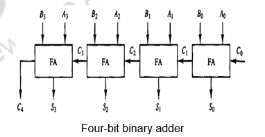
The digital circuit that generates the arithmetic sum of two binary numbers of length n is called an n-bit binary adder. It is constructed with n full-adder circuits connected in cascade, with the output carry from one full-adder connected to the input carry of the next full-adder. The Figure below shows the interconnections of four full-adders (FAs) to provide a 4-bit binary adder. The input carry to the binary adder is C0 and the output carry is C4. The S outputs of the full-adders generate the required sum bits. The n data bits for the A inputs come from one register (such as R1), and the n data bits for the B inputs come from another register (such as R2). The sum can be transferred to a third register or to one of the source registers (R1 or R2), replacing its previous content.
Binary Adder-Subtractor
The subtraction of binary numbers can be done most conveniently by means of complements. The addition and subtraction operations can be combined into one common circuit by including an exclusive-OR gate with each full-adder. A 4-bit adder-subtractor circuit is shown in Figure. The mode input M controls the operation. When M = 0, the circuit is an adder and when M = 1, the circuit becomes a subtractor. Each exclusive-OR gate receives input M and one of the inputs of B. When M = 0, we have B XOR 0 = B. The full adders receive the value of B, the input carry is 0, and the circuit performs A plus B. When M =1, we have B XOR 1=B’ and C0 = 1. The B inputs are all complemented and a 1 is added through the input carry. The circuit performs the operation A plus the 2’s complement of B. For unsigned numbers, this gives A – B if A >= B or the 2’s complement of (B-A) if A<B. For signed numbers, the result is A – B provided there is no overflow.
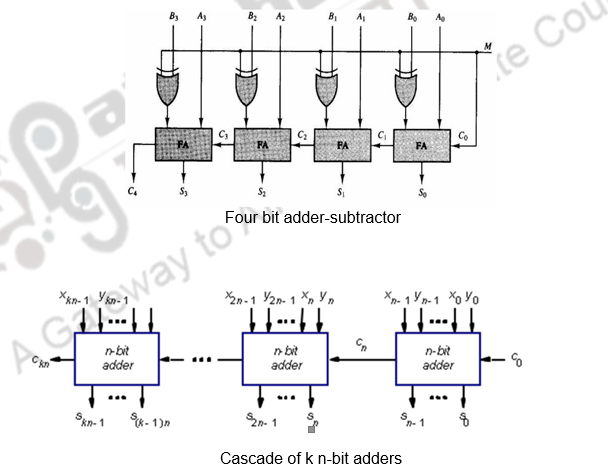
If you have to construct adders of larger sizes, these n-bit adder blocks can be cascaded as shown above.
Now, let us calculate the delay associated in doing a basic operation like addition. We know that combinational logic circuits can’t compute the outputs instantaneously. There is some delay between the time the inputs are sent to the circuit, and the time the output is computed. Let’s say the delay is T units of time. Suppose you want to implement an n-bit ripple carry adder. How much total delay is there? Since an n-bit ripple carry adder consists of n adders, there will be a delay of nT. This is O(n) delay. Why is there this much delay? After all, aren’t the adders working in parallel? While the adders are working in parallel, the carries must “ripple” their way from the least significant bit and work their way to the most significant bit. It takes T units for the carry out of the rightmost column to make it as input to the adder in the next to rightmost column. Thus, the carries slow down the circuit, making the addition linear with the number of bits in the adder. For example, consider the expressions for the sum and the carry.
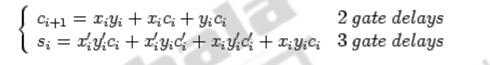
The carry takes two delays (a sum of products expression) and the sum takes three delays (one additional delay for the complement). Thus, as n increases, the delays become very high. Total time for computing the final n-bit sum from is 2(n-1) + 3 gate delays. When, n = 64, there will be 129 gate delays.
There are two ways to make the adder add more quickly. One is to go in for better technology, which again has its own limitations. The second option is to use more logic as discussed below.
Fast adders: Carry look-ahead adders
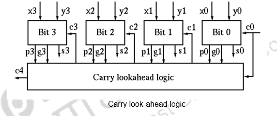
Carry lookahead adders add much faster than ripple carry adders. They do so by making some observations about carries. The bottle neck for ripple carry addition is the calculation of ci, which takes linear time proportional to n, the number of bits in the adder. To improve, we define gi, the generate function as gi = xi yi and pi, the propogate function as pi = xi + yi.
If gi = 1, the ith bit generates a carry, ci+1 = 1.
If pi = 1, the ith bit propagates a carry ci from (i-1)th bit to (i+1)th bit ci+1.
Both gi and pi can be generated for all n bits in constant time (1 gate delay).
ci+1 is either generated in the ith bit (gi = 1), or propagated from the (i-1)th bit (ci = 1 and pi = 1) (maybe both).
Now all ci’s can be generated in constant time (independent of n) of 2 more gate delays after gi’s and pi’s are available. This is illustrated below.
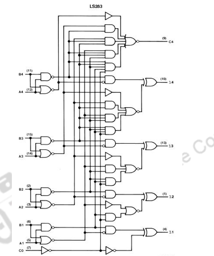

The above figure shows the logic diagram of the MSI chip 74×283 for a 4-bit adder All carries can be generated by the carry-look-ahead logic in 2 gate delays after gi’s and pi’s are available, and all sum bits can be made available in constant time of 6 gate delays, independent of number of bits in the adder.
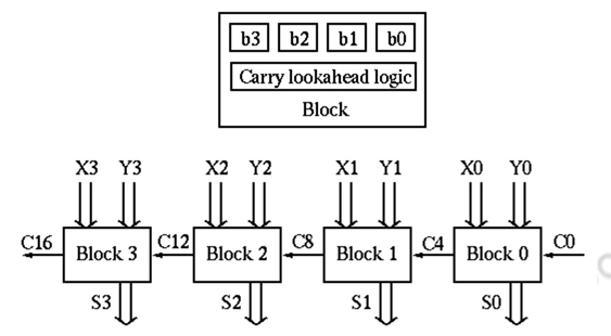
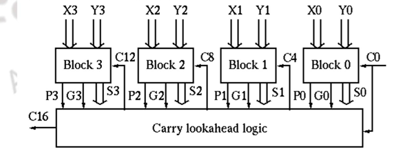
Two-level carry look-ahead : The carry look-ahead adder requires AND and OR gates with as many as (n + 1) inputs, which is impractical in hardware realization. To compromise, we pack n =4 bits as a block with carry look-ahead, and still use ripple carry between the blocks.
There are n / 4 blocks in an n-bit adder and the total gate delays can be found as:
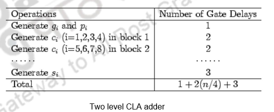
When n = 64, the number of gate delays is 36. To improve the speed further using the same idea, define 2nd-level generate and propagate functions:
P0 = p3p2p1p0
If all 4 bits in a block propagate, the block propagates a carry.
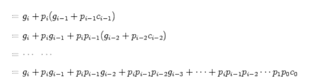
G0 = g3 + p3g2 + p3p2g1 + p3p2p1g0
If at least one of the 4 bits generates carry and it can be propagated to the MSB, the block generates a carry. Now c4 can be generated in constant time (independent of n):
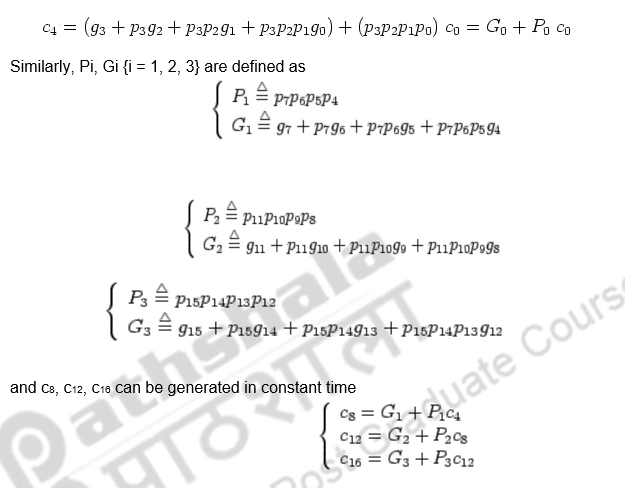
Combining 4 blocks of 4-bit carry-lookahead adder as a super block, we get a 16-bit adder with 2 levels of carry-lookahead logic.
There are n / 16 super blocks in an n-bit adder and the total gate delays can be found as:
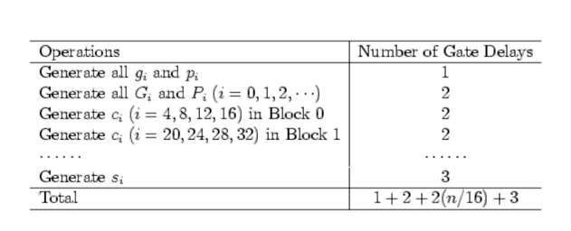
When n = 64, the number of gate delays is 14.
The very same idea can be carried out to the third level so that the carries, c16, c32, c48, and c64 can be generated simultaneously by the 3rd level carry-look ahead logic:

Binary multiplication
Multiplication of positive numbers
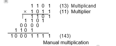
The manual multiplication algorithm carried out by hand and applicable to unsigned or positive numbers is illustrated below. Each bit of the multiplier is examined and either 0’s or the multiplicand are entered in each row, depending on the examined multiplier bit being a 0 or a 1, respectively.
The same multiplication can be implemented using combinational logic alone as shown below.
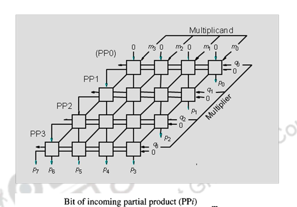
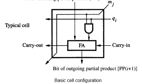
The basic cell has an AND gate which passes on 0 or the multiplicand bit, depending on whether the multiplier bit is a 0 or a 1. The full adder adds the multiplicand / 0, carry in and the partial product bit from above. Note the arrangement of this multiplier is similar in structure to the manual algorithm indicated earlier.
Multiplication can also be carried out using both combinational and sequential techniques. The adder in the ALU unit can be used sequentially. The algorithm, example and register organization are illustrated below.
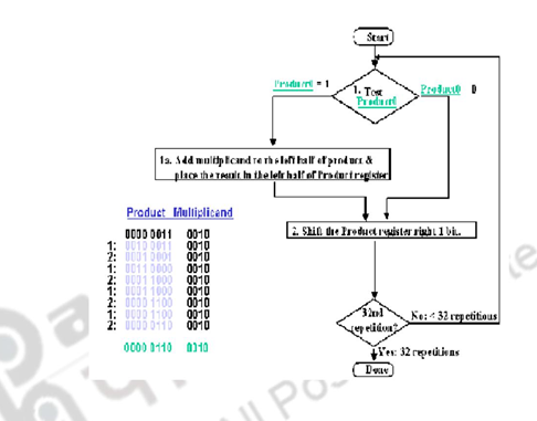
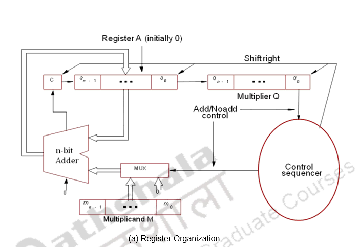
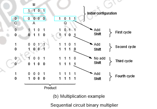
Register A is initially loaded with all 0’s, Q with the multiplier and M, with the multiplicand. The final double length product is loaded in A, Q. the control sequencer checks the LSB of the multiplier and gives the ADD / NOADD control signal. The MUX passes on the multiplicand or 0’s depending on the LSB bit. After the addition the product is shifted right, thus shifting out the checked multiplier bit and bringing in the next bit to be tested to the LSB position. This sequence is continued n times and the final product is available in A, Q. The simulation is given above.
The above technique holds good only for positive numbers. For negative numbers, the easiest way of handling is to treat the sign bits separately and attach the sign of the product finally. The other option for a negative multiplicand is to sign extend the 2’s complement of the negative multiplicand and carry out the usual process. But, if the multiplier is negative, this technique doe not work. So, the option is to complement both the numbers and then handle the negative multiplicand and positive multiplier.
There is yet another uniform method of handling positive as well as negative numbers. You will see that in the next module.
To summarize, we have discussed the fixed point arithmetic unit. We looked at binary addition, subtraction, fast adders – carry look ahead adders and binary multiplication techniques.
Web Links / Supporting Materials
- Computer Organization, Carl Hamacher, Zvonko Vranesic and Safwat Zaky, 5th.Edition, McGraw- Hill Higher Education, 2011.
- Computer Organization and Design – The Hardware / Software Interface, David A. Patterson and John L. Hennessy, 4th.Edition, Morgan Kaufmann, Elsevier, 2009.