|
|
|
|
|
|
|
|
|
|
|
|
|
|
|
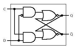
Flip-flops: D (delay) |
|
|
|
|
|
|
|
|
|
By adding a clock input C
and a control D, |
|
|
|
we can set or reset the
latch on a clock signal |
|
|
Characteristic table for
D (delay) flip-flop: |
|
|
|
|
D |
Q |
Q+ |
Operation |
|
|
|
|
0 |
0 |
0 |
reset |
|
|
|
|
|
|
0 |
1 |
0 |
reset |
|
|
|
|
|
|
1 |
0 |
1 |
set |
|
|
|
|
|
|
1 |
1 |
1 |
set |
|
|
(Fig. B.13) |
|
|
|
|
|
|
|
|
|
Note that the second
column is actually output, but it is used to generate the next state. |
|
|
The third column is the
output at a later time. |
|
|
|
|
When the clock value C
is 0, then the output of both AND gates is 0, so there is no change. |
|
|
|
(R and S inputs to NOR
gates are 0) |
|
|
|
|
When the clock value C
is 1, then the output of the AND gates is: |
|
|
|
|
|
D' for the first AND
gate, and D for the second |
|
|
|
|
|
This means that D acts
as a set when it is 1 and a reset when it is 0. |
|
|
|
Notice
that this arrangement eliminates the possibility that both set and reset will
be |
|
|
|
|
1 at the same time. |
|
|
|
|
|
|
|
|
|
|
|
|
|
|
|
|
|
|
|
|
|
|
|
|
|
|
|
|
|
|
|
|
|
|
|
|
|
|
|
|
|
|
|
|
|
|
|
|
|
|
|
|
|
|
|
|
|
|
|
|
|
|
|
|
|
|
|
|
|
|
|
|
|
|
|
|
|
|
|
|
|
|
|
|
|
|
|
|
|
|
|
|
|
|
|
|
|
|
|
|
|
|
|
|
|
|
|
|
|
|
|
|
|
|
|
|
|
|
|
|
|
|
|
|
|
|
|
|
|
|
|
|
|
|
|
|
|
|
|
|
|
|
|
|
|
|
|
|
|
|
|
|
|
|
|
|