|
|
|
|
|
|
|
|
|
|
|
|
|
|
|
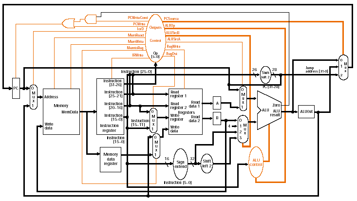
Multi-cycle datapath:
control signals |
|
|
|
|
|
|
|
|
|
|
|
What else is needed? Branches and jumps |
|
|
|
|
|
|
|
|
|
|
|
|
|
|
|
|
|
|
|
|
|
|
|
|
|
|
|
|
|
|
|
|
|
|
|
|
|
|
|
|
|
|
|
|
|
|
|
|
|
|
|
|
|
|
|
|
|
|
|
|
|
|
Possible sources for PC
value: |
|
Fig. 5.33 |
|
|
|
(PC + 4) directly from
ALU |
|
|
|
|
ALUout: result of branch
calculation |
|
|
|
|
Result of concatenation
of left-shifted 26 bits with upper 4 bits of PC (jump) |
|
|
Note
that the PC is updated both unconditionally and conditionally, |
|
|
|
|
so 2 control signals are
needed |
|
|
|
PCWriteCond: ANDed with
ALU Zero to control PC update for branch |
|
|
|
This result is ORed with
PCWrite |
|
|
|
PCSource: controls MUX to
select input to PC |
|
|
|
0: ALU result |
|
|
|
1: ALUOut |
|
|
|
2: Jump address |
|
|
|
Why do we need both 0 and
1 inputs? |
|
|
|
Control signals are
listed in Fig. 5.34 |
|
|
|
|
|
|
|
|
|
|
|
|
|
|
|
|