- Draw a 3-bit parallel load register. Use D flip flops.
Answer: See class notes
- Draw a 3-bit asynchronous counter. Use T flip flops.
Answer: See class notes
- Draw a Moore machine for a counter which counts 00, 01, 10, and
has a hold operation. Implement using T flip flops and a ROM.
Answer: Done in class.
- What's the difference between a Mealy and Moore machine?
Answer: A Moore machine has outputs that a function of inputs.
A Mealy machine has outputs that are a function of inputs and state.
- Come up with a Mealy machine, implement it using D flip flops.
Answer: Done in class.
- Write the characteristic table for D and T flip flops.
Answer: See class notes
- Write the excitation table for D and T flip flops.
Answer:
This is the excitation table for the D flip flop.
| Q |
Q+ |
D |
| 0 |
0 |
0 |
| 0 |
1 |
1 |
| 1 |
0 |
0 |
| 1 |
1 |
1 |
Notice that D and Q+ are the same.
This is the excitation table for the T flip flop.
| Q |
Q+ |
T |
| 0 |
0 |
0 |
| 0 |
1 |
1 |
| 1 |
0 |
1 |
| 1 |
1 |
0 |
- Explain the difference between characteristic tables and
excitation tables.
Answer: A characterisitic table has the control input
(i.e., D or T) as the first column, the current state as the middle
column, and the next state as the last column. Basically, it
tells you how the control bit affects the current state to produce
the next state.
An excitation table has the current state as the first column,
the next state as the second column, and the control bit as the
third column. Basically, think of this as the state you have
(first column), the state you want (second column), and what you
must set the control bit (third column) to get the desired state
you want. The excitation table is used to implement an FSM.
- How are excitation tables used to implement circuits?
Answer: You look at the column labelled qi
and the column labelled qi+. For each
row, you look at the value of qi and the value
of qi+, then go to the appropriate
row of the excitation table, and fill it for the column of the flip flop.
For example, suppose, for a given row, qi = 0
and qi+ = 1, then if you are using a T
flip flop to implement that row, you look at the 0, 1 row of the excitation
table for the T flip flop. It tells you that T = 1 (toggle), and
you write a 1 to toggle.
- Implement a T flip flop using D flip flops and logic gates.
Answer: I'll provide a partial answer. You would
have to write the truth table and draw the circuit to get the
full answer.
A T flip flop can be described by a finite state machine.
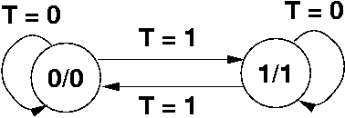
T is the input (normally, we use x, but really it's the input
for a T flip flop). Follow the usual steps of writing a truth table.
Use a D flip flop to implement, and use AND, OR, NOT gates, instead
of ROMs to implement.
In the FSM, if T = 0, that means hold, so it stays in the same
state. T = 1 means to toggle, so that switches to the other state.
- Explain state.
Answer: State is internal information (hidden variables)
used in conjunction with input to determine the output, and future
state. It represents the current status of the circuit or object.
- Suppose a FSM has N distinct states. How many flip flops are
required (at a minimum)?
Answer: ceil( lg N ) flip flops. Each state is
uniquely identified using ceil( lg N ) bits (as a UB number).
Since each flip flop stores one bit, you need that many flip flops.
- One flip flop can store how much information?
Answer: One bit
- What is a timing diagram?
Answer: It's a diagram that tells you what happens to,
say, the state and output, over time. The horizontal axis is time,
and the vertical axis is 0 and 1.
- Given a FSM, and a timing for some input, draw a timing diagram.
(Would only show up on challenge section---it's not hard, but you would
have to try it out once).
Answer: A set of class notes should hopefully appear
with this information in it (on Mealy/Moore machines)
- Draw an FSM that takes two bits of input at a time. These two
bits are bits i from two arbitrarily long strings. Assume the
two strings are being fed in from the most significant bits first to
the least significant bits. At time unit 1, An - 1 and
Bn-1 are fed to the machine. At time unit 2, An -
2 and Bn-2 are fed to the machine.
The FSM should output 00 if the two values are equal so far, 10
if string A has a larger value (assume UB), and 01 if string B has
a larger value.
Draw the FSM.
Answer:
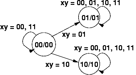
Basically, when you compare two n-bit strings, once you
determine one number is larger than the other, then it stays larger.
For example, consider X = 10100 and Y = 10011. The left most bit of
both is 1, so when we see XY = 11, we know so far, they're equal (with
the information provided). Then the next two bits are X3 =
0 and Y3 = 0 (which would be fed in as XY = 00). Again,
they're equal so far. Finally, we reach the third bit, where
X2 = 1 and Y2 = 0 (so XY = 10). At this point,
we know that X is larger than Y (and we go into state 10).
Even though more bits may be fed in, X will remain larger than Y.
To save space, we use one edge with multiple labels. Thus, XY = 00,
11 is equivalent to two edges, with one edge being labelled XY = 00
and the other edge being labelled XY = 11.
- Are we really going to answer general questions and have
definitions on the test?
Answer: For the most part, no. I think definitions make
good review questions because they stress ideas. However, I generally
put problems on exams that can be solved. Occasionally, there
will be a subjective question, just to see what you write.
- Combinational Logic is an implementation of what?
Answer: It's an implementation of Boolean functions.
- The behavior of a combinational logic circuit can be described
Answer: Truth tables or Boolean expressions.
- Name the gates used in combinational logic.
Answer: NOT, AND2, OR2,
XOR2, NAND2, NOR2,
XNOR2.
- Which logical operations are associative? Commutative?
Answer: NOT is unary, so it's neither. Of the rested listed above,
all are commutative. AND2, OR2,
XOR2, XNOR2 should be associative, while
NAND2 and NOR2 are not.
- What is a minterm?
Given n variables, a minterm is the conjunction (ANDing) of
n literals, where each variable appears in a minterm exactly
once.
Answer: It corresponds to a truth table of those n variables
where exactly one row has output 1.
- Come up with an arbitary truth table using 3 variables, and write
a sum of products expression.
Answer: Find rows with output of 1, create minterms for them,
and OR them. There should be examples from class notes.
- Write a truth table for a full adder.
Answer: See class notes
- Design a 3-bit ripple carry adder. What assumptions did you
make?
Answer: See class notes. Generally you assume that numbers
are represented in UB or 2C.
- Now modify the adder so that it has an additional output
V which is 1, if there is overflow, and 0 if not. What
assumptions did you make?
Answer: See class notes. Generally you assume that numbers
are represented in UB or 2C, and the overflow condition will depend
on which representation you use.
- Design a 4-1 MUX from 2-1 MUXes.
Answer: See class notes. There's an example in
the online class notes.
- Design a 5-1 MUX from any "smaller" MUXes (2-1, 4-1).
Answer: Use a 4-1 MUX and a 2-1 MUX. Feed the output
of 4-1 MUX into the 0 input of the 2-1 MUX. Feed x3,
..., x0 from the outside world to the 3, 2, 1, 0
inputs of the 4-1 MUX, respectively. Feed the x4
input from the outside world to the 1 input of the 2-1 MUX. Send
the output of the 2-1 MUX to the outside world.
- Write a Boolean expression for all outputs of a 2-4 decoder
with active-low enable, e.
Answer: Coming soon
- Define functional completeness.
Answer: Functional completeness refers to a set of gates
from which all truth tables (and Boolean expressions) can be implemented
from.
- What gates are functionally complete?
Answer: Here are some examples: { AND2,
OR2, NOT }, { AND2, NOT }, { OR2, NOT
}, { NAND2 }, { NOR2 }. The first set is not
minimal (in that, you can remove a gate and still have a functionally
complete set), while the others are minimal.
- Design a circuit that converts numbers from 3-bit 1C to
3-bit 2C.
Answer: Several ways to do this. You can use the
decoder-encoder trick (see the notes on this). You can also
use a 3-bit adder. Assume the adder has inputs x2,
x1, x0, y2,
y1, y0. Feed in X2,
X1, X0, from the outside world
to the x inputs of the 3-bit adder. Hardwire the
y2, y1 to 0. Feed in
X2, the sign bit, to y0. (Normally,
you would draw this, not explain it as I have).
If the 3-bit number is non-negative, this adds a zero. If
the 3-bit number is negative, this adds a 1. Recall that 1C is
flipping bits (for negative numbers), and 2C is flipping bits
and adding 1, so effectively, we add 1 when the 1C represenation
is negative.
- Assume the gate delay is T. Write a formula/expression for the
gate delay of an N-input AND gate implemented from 2-input AND gates.
Answer: You implement such a circuit like a balanced binary
tree of 2-input AND gates. The delay is the height of the tree
multiplied by T, which is ceil( lg N ) T.
- Why is OR2 different from OR3?
Answer: They are two different functions. One has two
inputs, while the other has 3.
- Implement OR2 using NAND gates.
Answer: Coming soon
- Let S be the set of Boolean functions have n bits as
input and 1 bit as output. What is the size of set S? Write
a formula.
Answer: 22n. That's because
there are 2n rows for n bits of input. For
each row, you can decide whether that row should be a 0 or a 1, thus
effectively, each row can be represented by a bit. With
2n rows there are m = 2n bits,
thus 2m =
22n possible functions (see class
notes on functional completeness, etc).
- What are the three types of MIPS instructions?
Answer: R-type, I-type, and J-type. These types
indicate the format of the instruction, not their purpose (thus,
branch instructions are I-type, not J-type).
- Each of the three types has different parts. Indicate
which bits are used for what. (e.g., which bits are used for the
opcode, etc).
Answer:
For R-type instructions
- B31-26 Opcode
- B25-21 Register s (first source register)
- B20-16 Register t (second source register)
- B15-11 Register d (destination register)
- B10-5 Shift amount (for shift instructions)
- B4-0 Function
For I-type instructions
- B31-26 Opcode
- B25-21 Register s (source register)
- B20-16 Register t (destination register)
- B15-0 Immediate
For J-type instructions
- B31-26 Opcode
- B25-0 Offset
- What are the alternate names of the registers (e.g.,
$v0, etc.)?
Answer:
- $v0, $v1 (Return values)
- $a0, $a1, $a2, $a3 (Arguments to functions)
- $t0,...,$t9 (Temporary registers---not saved by callee)
- $s0,...,$s7 (Saved registers---saved by callee)
- $sp (Stack pointer)
- $ra (return address, used in jal and jalr)
- $zero (hardwired 0)
There are a few other registers too ($gp is the global pointer,
$fp is the frame pointer, and a few registers used by the assembler
or the OS), which you don't need to worry about.
- Implement the following function in MIPS using the conventions
given in class and the book:
int sum( int n )
{
  if ( n <= 0 )
     return 0 ;
  else
     return n + sum( n - 1 ) ;
}
Answer: This answer is quite similar to the fact
function from the book.
sum:   addi $sp, $sp, -8    # Make space for 8 bytes
       sw   $a0, 0( $sp )   # Push n
       sw   $ra, 4( $sp )   # Push return address
       bgt  $a0, $zero, ELSE  # branch to else
       addi $sp, $sp,  8    # Restore stack pointer
       addi $v0, $zero,  0  # Set return value to 0
       jr   $ra             # jump back
ELSE:  addi $a0, $a0, -1    # n--
       jal  sum             # recursive call
       lw   $a0, 0( $sp )   # Pop n
       lw   $ra, 4( $sp )   # Pop return address
       addi $sp, $sp,  8    # Restore stack pointer
       add  $v0, $v0, $a0   # Add n to result in $v0
       jr   $ra             # jump back
- jal puts the return address in a register. Is this
helpful? What are potential problems?
Answer: In older ISAs, return addresses were always pushed
on the stack. However, stack is memory, and memory is much slower
than registers. So, if you use registers, you can be much quicker.
The drawback is when the subroutine being called has another
subroutine call. To prevent the return address from being overwritten,
the register is pushed on the stack. Thus, you might only save
pushing the return address to the stack by one step. The savings
is somewhat small, but apparently enough for the MIPS people to decide
storing the return address in a register.
- Suppose you want to push $s0 and $s1 onto the stack. Write
the MIPS instructions to do this.
Answer: MIPS has no push instruction, so you have to
adjust the stack pointer yourself. Each register stores 4 bytes,
so you need to make space for 8 bytes.
   addi $sp, $sp, -8   # Make space for 8 bytes
   sw   $s0, 0( $sp )  # Push $s0
   sw   $s1, 4( $sp )  # Push $s1
- Suppose you have an array with label arr. The size
of the array is in register $a0. Furthermore, you have a system
call to print integers. To make the system call, you do:
  li $v0, 1      # 1 means to print_int, li means load immediate
  li $a0, 10     # Puts the value to be printed in $a0
  syscall        # Prints the value
You may assume you have a la $rs, label instruction which
loads the address given by label into register $rs
Implement as a loop.
Answer: Coming soon
- Implement as a recursive function (write it in C first, then
translate)
Answer: Coming soon
- Explain caller-saved and callee-saved registers.
Answer: All subroutines share the same set of registers.
So, when you make a jal call, the subroutine being called
(the callee) will need to use the same registers. So,
the question arises: whose responsibility is it to save registers
on the stack?
There are two conventions. Caller-saved makes the
caller responsible for saving registers it wants prior to calling
the subroutine. This tends to be safer, but may involve saving
more registers than necessary (after all, what if the callee uses
few registers?).
Callee-saved makes the responsibility of saving on
the called subroutine. The callee saves registers it uses, but
no others.
I like to compare this to blackboard erasing. Who's responsibility
is it to erase the blackboard (or whiteboard)? The lecturer who wrote
on the board, to make it neat for the next person? (I think that's
closer to caller saved) Or the lecturer who's coming in, who must
erase what the previous person wrote. (I think that's closer to
callee saved).
MIPS uses both kinds. The $s0..$s7 registers are callee-saved,
and $t0-$t9 needs to be caller saved, assuming you want these registers
preserved after a subroutine call.
- How is an address computed for a jump instruction?
Answer: You concatenate PC31-28 (the
top 4 bits of the PC), to IR25-0, (the 26 bit
offset of the J-type instruction), to 00, to create a 32 bit
address.
- How is an address computed for a branch instruction?
Answer: Shift the 16 bit immediate left by 2 bits (to
create an 18 bit value). Sign-extend the 18 bit value to 32 bits.
Add to PC.
- How is an address computed for a load instruction?
Answer: Sign extend the 16 bit immediate to 32 bits. Add
to the contents of the register specified in the instruction. This
may cause an exception if the address is not word-aligned.
- Give the names of the various kinds of addressing modes.
Answer: See page 151 and 152 of the textbook.
- Immediate addressing This uses the immediate value.
Personally, I don't consider this an addressing mode (since it
doesn't involve addresses).
- Register addressing This uses the value stored in a
register. Personally, I don't consider this an addressing mode (since
it doesn't involve addresses). The exception is for jr (jump
register), which uses the 32 bit value in a register as an address.
- Base addressing This adds an immediate value (usually
sign-extended) to a register to create an address in memory.
Load/store instructions use base addressing.
- PC-relative addressing This adds an immediate value
(usually sign-extended) to the PC to create an address in memory.
Branch instructions use base addressing.
- Pseudo-direct addressing Use bits from the PC and
the 26-bit offset to generate an address. Jump instructions
use pseudo-direct addressing.
Miscellaneous
- Draw the CPU given in the handout on Thursday.
Web Accessibility