CMSC 298M Lab Assignment - BYO-bot January 5, 2005
Due by Friday, January 14th - just need to show it to me after class or
in lab.
For this assignment you have to put together a BYO-bot (designed by
David Miller and Randy Sargent at www.kipr.org). You will be given a kit
with all of the parts necessary and access to any equipment
(soldering iron, glue gun, ...) needed. When you have finished putting
together your BYO-bot, you need to let me see it - whether it works or not -
to get credit for completing the project. You can show it to me during one
of the hours when I am in the lab, or else after class.
In the process of putting your BYO-bot together, make sure that you take the
time to first understand what is going on in the circuitry, before soldering
wires/pins together. Also, before any hot gluing/taping should occur, all of
the soldering should be completed; So test it before taping the motors down
- and make sure the motors are driving in the right direction. And
another reason to take your time in doing this, is that there are little to
no spare parts.
Contents of the kit (ziplock bag): 2 light sensors, 2 transistors, 2 motors,
1 battery pack, 1 circuit board, 2 AA batteries, and 2 'wheels' (one rubber
tube you cut in half).
Extra material needed, but not in the kit (however it is in the lab, with the
exception of the batteries): red and black wire, solder/soldering iron,
glue/hot glue gun.
(Abridged) Directions:
- If you have never soldered before (or haven't in a long time) I
suggest practicing on a couple strips of wire (preferably solid core).
- Next examine the back/bottom side of the circuit board and where the
next couple steps say the sensors and transistors and motors should be wired
in. The bottom side of the circuit board, is the side with the 'metal' on
it. And follow the 'current' and make sure you understand how it (all of the
circuitry together) works.
- Here is a picture of the circuit board's top side (with the holes
numbered for the following steps):
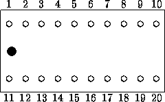
Note - the "top" side is the side without the metal etching on it.
- One transistor goes into holes 4, 5, and 6 (base in 5, collector in 4,
and emitter in 6), and the other goes into holes 14, 15, 16 (coll. in 14,
base in 15, and emit. in 16). The following diagram shows the collector (c),
base (b), and emitter (e) for the transistors included in your kit (the pin
on the left is the emitter - the gif didn't get created too well - so it
should go e b c - not c b c):

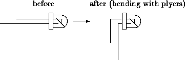
- One light sensor goes into holes 2, and 3 (the LONGER end should go
into 2 and the shorter end into 3 - see diagram for 'preparing' the sensors).
The other sensor goes into holes 12, and 13 (similar to the 1st sensor).
- One red wire (about 3 inches long) will go into hole number 7 (strip
off just as much as needed from the end to expose the metal wire inside), and
then attach the other end of the wire to the RED terminal on the motor (this
motor will drive the LEFT 'wheel'). One black wire (again about 3 inches
long, and just cut it from one of the spools in the lab) will go into hole
number 8, and then to the other terminal on the same motor.
- One red wire will go into hole number 17, and then to the NON-RED
terminal on the motor (this motor will drive the RIGHT `wheel'). One black
wire will go into hole number 18, and then to the other terminal on the same
motor as the red wire from hole number 17.
- The final part of the circuit to attach is the battery pack. The
red wire (which you may want to trim to be about 2 inches long) will go into
hole number 1, and the black wire (again trim it) will go into hole number
11.
- The order in which I would solder the components is: transistors,
sensors, motors, battery pack, done. You don't have to do it in this order
if you don't want. Remember to tin the iron, and the ends of the wires.
- Now the last thing to do is put together the 'mechanical' parts of
the BYO-boy - and all this entails is gluing (or taping if you prefer -
using double sided tape) the circuit board to the top of the battery pack,
gluing the motors to the piece of white 'cardboard', and then gluing the
'cardboard' to the back of the battery pack. And finally, attach the
'wheels' (remove the
little gears if they are still on the motor) and plug in a battery and watch
your BYO-bot go!
Currently (assuming all the wiring and soldering was done right) your BYO-bot
will follow light. How could you modify the BYO-bot so that it:
- Moves away from light?
- Tries to find a dark (or shaded) area in the room?
- Would circle a light placed on the floor next to it?
Web Accessibility