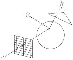
Figure 1: Ray tracing [4].
One of the simplest and most realistic methods for image synthesis originated in the field of physics. Here, photons of light are traced as rays from their source through the scene. A photon of light that leaves a light source hits an object. Some of its energy is absorbed and some is reflected. The reflected portion of the photon of light may continue to be reflected off of other objects in the scene. It may hit a transparent object and be refracted. The rays of light that finally enter our eye are what we see [4].
This process of following rays of light is called "ray tracing" and is considered to be one of the most popular and powerful techniques in the image synthesis repertoire. With a three-dimensional model of a scene and infinite amount of time, ray tracing techniques can generate stunningly accurate images [2]. The main problem is that most of the light that leaves the light sources never hit our eye. Consequently, the vast majority of computation of light ray pathways is wasted.
If the ray hits an object then the intensity of the reflected light at this point is calculated by determining which light sources are visible. This is done by tracing rays from the point of intersection to the light source. If any of these rays succeed in reaching a light source before hitting another object, then the light source illuminates the object. If not, then a shadow is cast on the object.
Using the direction to the light source, the direction to the viewer, the perpendicular to the point of intersection, and the intersected object's color, the pixel's color can be calculated. This simply needs to be repeated for all of the pixels in the grid to generate our image.
Two factors complicate this simple model. The first arises because of the simplifying assumption that the light that illuminates a point on an object arrives directly from the light sources. This totally ignores the possibility that light might be arriving indirectly from other objects in the scene. Since indirect illumination could arrive from anywhere in the scene, it is quite difficult to model. Typically indirect light is modeled as ambient light that illuminates every point in the scene.
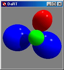
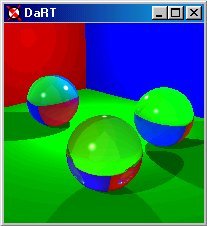
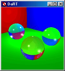
The second complication arises from highly reflective or transparent objects in the scene. In the case of reflective objects, such as mirrors or shiny objects, a reflective component must be taken into consideration. Using an associated coefficient of reflection, the portion of the ray that is reflected is calculated and recursively traced through the scene. In the case of transparent objects, such as glass balls, a refracted component must be taken into consideration. An index of refraction is used to calculate a refracted ray that is also recursively traced through the scene. When each of the reflected or refracted ray-trace colors is returned, it is factored into the color of the pixel at that point. In this way, highly reflective and transparent objects can be modeled [3].
In order to achieve photorealistic images, millions of rays representing individual rays of light need to be cast and traced through the scene. In addition, the reflected and refracted portions of each individual ray of light needs to be traced until the there is no energy left. This requires considerable computational time even on the fastest of today's machines and even the smallest of images can take a significant amount of time to render. Certainly nobody wants to wait 15-60 seconds just to realize that the image was not what they really wanted and then have to do it again. This was the motivation for the development of an Interactive Ray Tracer.
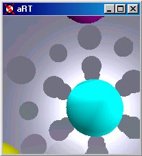
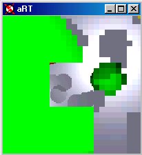
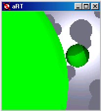
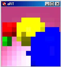 (a) Image at 1/16th resolution. |
 (b) Image at 1/8th resolution. |
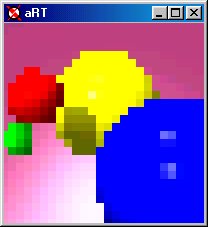
 (c) Image at 1/4th resolution. |
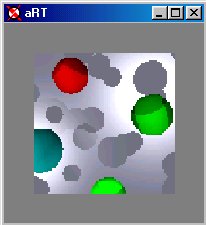
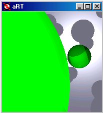
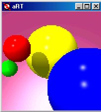 (d) Image at half resolution. |
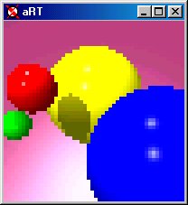
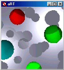
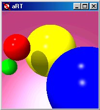 (e) Image at full resolution. |
By providing immediate feedback to the user, aRT allows the user to make decisions regarding the position of the camera before waiting until the entire image is rendered. Using the arrow keys or mouse, the camera can be panned in the desired direction. In addition, the camera can be moved in and out using 'I' to move in and 'O' to move out. Moving the camera interrupts the process of rendering, adjusts the image and then continues to render.
In order to facilitate interactive movement of the camera and subsequent image generation, a data structure is used to store state and color information of the image. By storing this information, image data can simply be read from the data structure rather than recalculated every time the camera is repositioned.
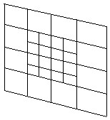
Several difficulties arose from using the quadtree:
Rays are cast at each level of the mini-quadtree, but the results are stored only in the lowest level. This, in addition to the removal of the upper-most levels of the original quadtree, reduces the number of rays that need to be cast by at least 25%. Reducing the number of rays also reduces the computational time required to generate an image thus speeding up rendering.
Two additional features of aRT help to decrease the rendering time. The first is the ability to toggle the reflections and shading by pressing the 'R' key on the keyboard. This reduces the computational time of rendering the scene by eliminating all recursive traces through the scene. Only the color of the original object of intersection is used to determine pixel color producing a flat image.
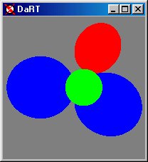
The second is the ability to toggle the shadows by pressing 'S' on the keyboard. In this case, computation time is reduced because the rays back to the light sources are omitted from the trace producing an image without shadows.
By using the imagetree rather than the quadtree, the number of rays that must be traced to generate our image is reduced. This decrease in rays results in a decrease in computation time and, thus, a decrease in the render time. In addition, the imagetree allows for the implementation of the camera motion in an efficient manner.
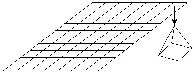
The implementation of a rotation of the camera is accomplished by translation in the horizontal and vertical directions. As this is a primary goal of aRT, the top level of our chopped quadtree is stored as a two-dimensional array of imagetree nodes. In this way, whenever the camera is rotated, a quick shift in the secondary quadtrees results in a shift in the image.
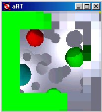
 (a) Image before camera is panned down and right. |
 (b) Immediately following the pan of the camera, the current picture is shifted. |
 (c) Image continues to render at the highest level of the imagetree at 1/16th resolution. |
 (d) Rendering continues at 1/8th resolution. |
 (e) Half resolution. |
 (f) Full resolution after the camera movement. |
In an effort to give the program a "memory" the two-dimensional array of imagetree nodes is 50% larger in each direction than the window. Thus it is able to store information so that if the camera is moved in one direction and then back again, the data structure remembers the rays that have been cast and they do not have to be retraced, just read from the secondary data structure.
Moving the camera in and out is more complex due to the nature of the movement. Whenever the camera is moved in or out, not only is there an enlargement or reduction in the current image, but the visual relationships among objects in the image can shift. Two factors determine the amount of this shift: the distance of the objects from the camera and the distances of the object from the middle of the image. Objects that are closer to the camera tend to shift more than objects that are farther away. Likewise, the farther from the middle of the image, the greater this change can be. As such, the data that is already in the imagetree is suspect and must be recalculated. Moving the camera in and out requires that much of the traced data be thrown out to be retraced. Thus, the movement of the camera includes the initial guess based on the current image and then retracing and redrawing the outer areas of the image. How much data is discarded depends on the distance from the middle of the image.
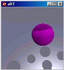
 (a) Before moving the camera out. |
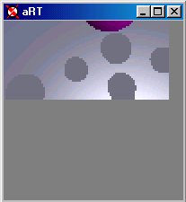
 (b) Immediately following the move, the current picture is reduced. |
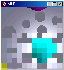
 (c) Image continues to render in decreasing resolution from the center. |
 (d) 1/8th resolution. |
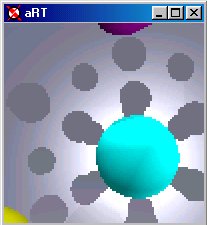
 (e) Half resolution. |
 (f) Full Resolution. |
A great deal of work still needs to be done in order to realize the full potential of the imagetree data structure. Several ideas immediately come to mind: