By Tzu-hsiu Chiou
Supervised by Dr. David Mount
May 2004
Run the flocking motion Java applet
Download Source for Java Applet
Roadmap-Based Methods for Flocking Motion with Obstacles
By Tzu-hsiu Chiou
Supervised by Dr. David Mount
University of Maryland, College Park
May 2004
Abstract
The goal of this project is to create algorithms for controlling the motion of a group of entities in an environment with obstacles. In our research, we added new rules for flocking behavior, devised our own path-finding algorithm, and incorporated a number of optimizations. The result is an algorithm that allows accurate and efficient simulation of autonomous groups of objects in a complex environment.
The ability to maintain flocking (or group) motion for multiple moving objects is an important subject in computer science. Applications of flocking motion include simulating groups of artificial life, or animating troop movements in real-time strategy games.
There are two main directions in the design of group motion systems. One is for simulating natural life, in which we try to simulate the behavior real-life herding animal like school of fish or herd of sheep. The purpose is to make the simulated entities look as natural as possible. In this direction, the algorithms typically do not have to deal with complex environment, and in 1987 Reynolds presented a flocking behavior model that allows almost natural looking animation of the a flock of birds[6].
The other direction is maintaining objects under motion in complex environment, with lesser consideration to the reality of the motion. In this case, the object can be a group of robots; and the goal is to reach the destination as fast as possible while maintaining as a group. This direction is more closely related to robotics and artificial intelligence. The algorithm has to deal with obstacles and complex environments. The subject of this project is for this latter type of motion, and our particular focus is on developing a roadmap-based algorithm for flocking motion in complex environment.
The first flocking model was introduced by Reynolds in 1987 [6]. The flocking model that Reynolds presented exhibits good flocking behavior for entities moving in free space. However, the model does not deal with complex environments. The obstacle presented in ReynoldsË research is simple circular shaped obstacle. And in current applications, games in particular, require the coordination of a large number of objects across complex obstacles.
The most common path search algorithm for games is A* approach, in which each individual entity (or troop) searches for a path by dividing map into grid [7]. Because each entity works independently, this approach can easily lead to units getting stuck at narrow spots and may lack coordination of a group.
In 2002, Bayazit, Lien and Amato introduced a road-mapped based roadmap method, which used probabilistic roadmap approach (PRM) for path planning[1]. Their algorithm leads to great goal finding abilities; however, the group falls apart easily.
In 2003, Kamphuis and Overmars proposed a method to simulate the group as a deformable shape and to use PMR to find the path [4]. Their approach achieved moving entities as a coherent group. However, the movement of the group is too restrictive. For example, their group cannot separate temporary to maneuver around small obstacles.
The goal of this project is to develop efficient an algorithm for Ÿgood÷ flocking motion in a complex environment. By Ÿgood÷ flocking motion we want the entities to stay in a group as much as possible, however, we allow some degree of separation; and we want a natural looking group motion. The paper will also present an algorithm to guide a group of entities from some given point A to point B, which is also referred to as homing behavior. This is most common and perhaps important action as a group. Although there have been a couple roadmap-based methods developed for complex environments, all of them have some weaknesses. Bayazit, Lien and AmatoËs method provides great path finding, but lacks the good flocking behavior [1]. And Kamphuis and OvermarsË method lacks flexibility.
In our research, we improve the flocking behavior by adding new rules for Ÿlocal÷ behavior and improve path finding with our path-finding algorithm. Furthermore, we try to utilize the information sharing entities in a group in order to reduce the time for path finding and improve flocking behavior.
There are three essential parts of flocking motion with obstacles. The first part is flocking, also referred as local behavior, which dictates how each entity moves in reaction to the others. The second part is path-finding or global behavior. This section covers how the group finds a path to the goal through the complex environment. The third and last part involves combining local and global behavior. This section explains how to combine local and global behavior.
Flocking behavior is a natural phenomenon. When relative simple animal gathers together, they frequently exhibit amazing coordination as a group. Some examples include schools of fish, flocks of bird, and herds of sheep. There are certain simple rules that each animal follows as a member in the group that together result in coherent motion.
Before going into in more detail on to how we can simulate animal group motion, we should understand why animal flocks in nature. One of the major reasons for animal flocking behavior is to decrease the anxiety. Several experiment haven been performed on how a different number of sheep negotiate a maze. And the results showed that when the sheep is alone, it shows sign of stress; however, when there are four or more sheep are gathered, they will move together and learn faster then a single sheep [3]. The second reason has to do with avoiding predator. In a group, animal would warn each other of possible threats. The other reason, which is used by birds, is to reduce drag when flying in a formation. What we can learn from animal behavior? Forming groups allow better survivability through information sharing.
Flocking motion also referred to as local motion because it controls the motions of current entity in relation to neighboring entities. In contrast to local motion, global motion determines the overall motion of the entities. Next we describe the algorithm we used to implement flocking behavior.
2.2 ReynoldsË Three Rules for Flocking/Herding Behavior
In 1987, Reynolds proposed three rules for simulating flocking behavior. ReynoldsËs insight of group behavior is that each entity follows relative simple rules; but, when taken as a whole, they move as an organized group. As pointed out by Reynolds, there are three rules, 1) separation, 2) alignment, and 3) cohesion. The direction an entity is moving is the sum of the above three force and the entityËs original vector. Also, in Reynolds paper refers to each the moving entity as Ÿboid,÷ and we will use this term for the rest of the paper. (See Appendix A for a description of the origin of the term Ÿboid÷).
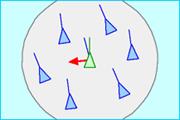
The first rule, separation states that a boid should move away from another boid when two of them are too close (See Figure 2.1.1 for an illustration from ReynoldsË website [6]). This rule ensures there are spaces around each boid.
We implemented this rule by defining a range around each boid which we denote as the Ÿrepulsion range.÷ If two boid get too close, a repulsion force vector is generated away from each other. The total repulsion vector for a given boid is generated by summing all the repulsion forces from other boids within the repulsion range.
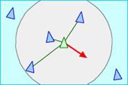
The second rule, alignment indicates that a boid should move in the general direction of the neighboring boids. This rule aligns each boid to the direction that the group is moving toward (see Figure 2.1.2).
We implemented this rule by defining a vision range around each boid. And we sum up the directions the neighboring boids are heading within the range to get an alignment vector.
|
|
|
|
|
Picture taken from ReynoldsË website <http://www.red3d.com/cwr/boids/> |
||
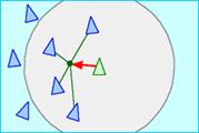
The last rule cohesion indicates that a boid should move to the center of its local neighborhood. This rule ensures that each boid will stay close to the group (until the repulsion force starts pushing it away from the group).
We implemented this rule by calculating the center of the neighbor boids within the range, and then we calculate a vector from the current boid to that center point and get a cohesion vector.
Although ReynoldsË model produces a nice flocking behavior, we need more rules to adjust the model to a complex environment and to improve overall behavior. The rules we implemented are 1) in-sight and 2) catch up.
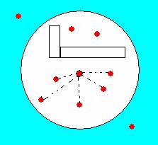
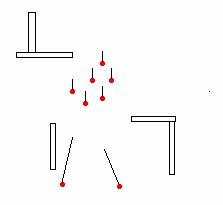
The first rule is in-sight which means that a boid can only be affected by another boid that has no obstacle between the two. This rule prevents a boid from attempting to reach a larger group on the other side of the obstacle, which would result in repeated collisions with the obstacles (See Figure 2.3.1 for details). The implementation of this rule is straight forward. We run a check to make sure there are no obstacles between the boids before calculating the forces that affects the current boid.
|
|
|
|
Dot line indicates the neighboring boids that the current boid can interact to. |
The black line indicates the directional vector for each boid. The boids in the group has smaller vectors, while left-behind boids has larger vectors to Ÿcatch up÷ to the group |
The second rule, catch up, is to ensure that individual boids that falls behind will move faster, and therefore catch up to the group. This rule is implemented to help the boids to stay in a group. With out this rule, the separated boid might never catch up to the group, because either the group is moving too fast or the separated boid is moving too slow.
This rule is achieved by two steps. At first, we set a cruising speed for the group by choosing speed that any boids which are left behind can catch up easily. In addition, any boid that is behind will accelerate.
We implemented this rule by searching a viewing angle in front of a boid to see if there are any other boids in the front and outside the detection range. If another boid is detected that is in the front and outside the detection range, the current boid will speed up. Other wise, the current boid will slow down until reach a pre-defined cursing speed for the group. See Figure 2.3.2 for an illustration.
For the boids to navigate through a complex environment, they need a path finding algorithm. We use probabilistic roadmap (PRM) method to generate a roadmap, then run our path finding algorithm to produce the path.
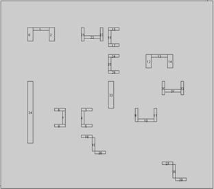
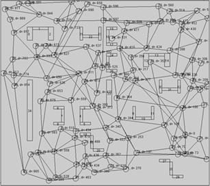
3.2 Construction of Probabilistic Roadmap
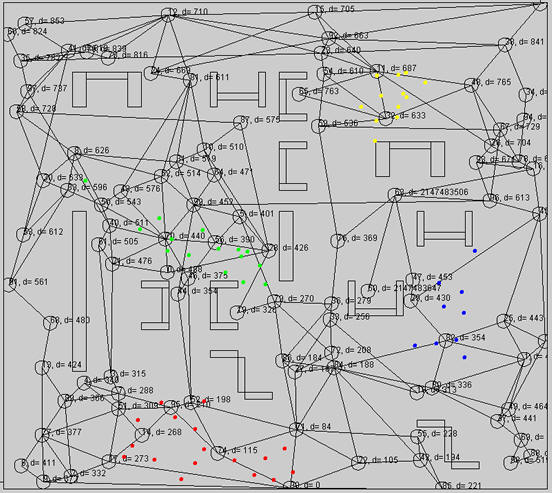
A roadmap is a graph that contains vertices and edges, where each edge represents a clear path. Probabilistic roadmaps (PRM) are first mentioned by Kavraki, Svestka, Latombe, and Overmars in Probabilistic Roadmaps for Path Planning in High-Dimensional Configuration Spaces. The PRM is generated by inserting random vertices onto the map, and then trying to connect the vertices with existing vertices if there are no obstacles in between. The advantage of PRM is that it is easy to implement, efficient, practical, and works well most of the time. The main disadvantage for PRM is this method does not work very well, if the graph mostly occupied with obstacles (In this case other variations of PRM are needed). Figure 3.2.1 and 3.2.2 give examples of PRM generated road maps by our program.
The creation of the PRM includes two steps, which are covered in Section 3.2.1 and 3.2.2.
|
|
|
The algorithm we used to generate PRM will first generate V vertices using random number, V is defined by the user depending on how dense the user wants the map to be. Of course a vertex can not lie on an obstacle, if that is the case, we run the random number generator again to search for a new location. There are two problems we had to solve when generating vertices. At first, to prevent vertices from clustering together, we have a minimal distance restriction between two vertices.
At second, we created a buffer region around each obstacle when generating vertices; the width of the buffer region is a minimal distance restriction between obstacle and the vertices. This is done so that PRM vertices would not lie too close to the obstacles. And this creates a wider path, so that the boids will be less likely to collide with obstacles.
The second part of the generating PRM algorithm is to connect the vertices; basically we check all the pairs of vertices and add the edge if there is no obstacle in between.
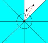
One problem with the above algorithm is that it may create duplicate edges that lead to the same vertices. One algorithm we developed to reduce this particular problem is to limit the number of edges in each direction. For each vertex v, we divide surrounding of v into N sectors; N is a predefined number control total number of sectors. For all edges connect to current vertices, only shortest edge in each sector is stored. In Fig 3.2.1, a node has 8 sectors. The red dotted edge is removed because the existence of a shorter edge. This removing-extra-edge algorithm is used to reduce the number of edges in the graph, and therefore improve the run time for shortest path algorithm.
|
|
|
Fig 3.2.3: remove extra edge in each sector |
After generated a road map, we need an algorithm that guides the boids to the destination. For our approach, a boid will constantly running the path-finding algorithm, which will lead the boid to a sub-goal. A sub-goal is a vertex in the graph that guides a boid toward the goal. We make sure a sub-goal is in-sight to the boid, so the boid can reach the sub-goal by simply moving toward the direction of the sub-goal. The path-finding algorithm we used to located next sub-goal contain three steps 1) construct shortest path graph 2) find closest node and 3) find the next in-sight sub-goal.
To generate the shortest path, we run DijkstraËs algorithm ****reference from the destination vertex. This will produce shortest paths from all other vertices to the destination vertex, so we only need to run DijkstraËs algorithm once. Also, we only need to calculate the shortest path graph once, whenever the destination is changed.
After obtaining the shortest path graph, a boid will search for the closest in-sight node around. Then we run a search for all the nodes in the shortest path from the closest in-sight node to the destination; we search for the node that is closest node to the destination that is also in-sight to the current node.
The main advantage of this approach is, instead of using the PRM to get a path this algorithm uses the vertices as guidance to get closer to the goal. Therefore, at any time, this path-finding algorithm will guide a boid to a sub-goal that is closer to the goal.
See Figure 3.3.1 for an example.
|
|
|
Vertices are in black, and the boid is in red. The red path shows a boid take a short cut, instead of following the road map (black dot path). |
Although the PRM path-finding method helps the boids avoid most of the obstacles, collisions are still possible. The boids will often be pushed into obstacles by other group members because of the flocking behavior forces. For most other implementations the boid that run into an obstacle will simply collide with obstacle until it is free. The path-finding algorithm we proposed will help the boid escape by recalculating a new path whenever a boid collides with an obstacle. The boid can follow the new path to get around the obstacle.
4.1 Combining global and local behavior
The path-finding with PRM will help the boids to avoid most of the obstacles and the flocking behavior will keep the boids close together. However, by taking advantage of information sharing within a group, we can make the algorithm run even faster.
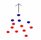
One of the innovations that we developed is to let boids at front to lead the group. If we simply put the global and local behavior algorithm together, every single one of the boids will run the path finding algorithm. Our idea is to let the boids in the front of the group run path finding algorithm while the rest of the group will follows these leaders. As a result, only a limited number of boids will run path-finding algorithm, and therefore improved the performance. Another advantage of this approach is that individual boid will less likely to break away from the group from following another path.
This main difference between our leader and other approachËs leader is that we do not have a fixed leader. Any boids that happens to be moving in the front of the flock will take over the leader role. This approach permits the freedom for the boids to separate into different groups.
We implemented this by checking number of boids in a viewing arc for the current boid. If there are more than a predefined constant (we used 4) then the current boid will not run the path-finding algorithm, which saves some calculation time. Otherwise, the boid will search for the next node by running the path-finding algorithm.
|
|
|
Fig 4.1.1: Leading The blue boids Ÿleads÷ rest of the group |
In this paper, we introduced algorithms for more efficient and intelligent flocking behavior in complex environment. We achieved this by adding rules for flocking behavior and introducing new algorithms for path finding. Furthermore, we optimized the algorithm by allowing only a small number of boids to run the path-finding algorithm.
Although our algorithm provides fairly natural and intelligent motion of boids, there are a couple directions for further improvement. The first, improvement is to have control over the degree that the boids are allowed to separate. In one extreme, the boids can be a completely coherent group as shown in Kamphuis and OvermarsËs paper ŸMotion Planning for Coherent Groups of Entities÷ [4]. Other approaches allow the boids to separate for a certain amount of time before regroup again. This might be able to be achieved by dynamically changing graph weight.
Another improvement is
for boids to steer away from obstacles. We experiment with this idea by using a
repulsion force away from obstacles; however, from our result the repulsion
force interfered with the boidsË motions, for example this obstacle repulsion
force tended to push boids away from a small gap.
Reference
[1] Bayzait, Lien and Amato. Simulating Flocking Behaviors in Complex Environments. http://parasol-www.cs.tamu.edu/dsmft/research/flock/
[2] Cormen, T. H.; Leiserson C. E.; & Rivest R. L. (1990) Introduction to Algorithms. MIT Press. ISBN 0-262-03141-8
[3] Dinger. Understanding Sheep. http://www.ceresfarm.co.nz/understandingsheep.htm
[4] Kamphuis and Overmars. Motion Planning for Coherent Groups of Entities.
www.give.nl/movie/publications/utrecht/groups_icra2004.pdf
[5] Kavraki, Svestka, Latombe, and Overmars. Probablistic Roadmaps for Path Planning in High-Dimensional Configuration Spaces. IEEE Transactions on Robotics and Automation, 12(4):566-580, 1996.
[6] Reynolds, C.W. 1987 Flocks, herds, and schools: A distributed behavioral model. In Computer Graphics, 25-34
[7] Russel and Norvig. Artifical Intelligence: A Modern Approach. Prentice Hall, 1994.
"Boid" was an abbreviation of "birdoid", as his rules applied equally to simulated flocking birds, and schooling fish.
It was also inspired by a graphics modelling and rendering system by Tom Duff when he was at the Computer Graphics Lab of the New York Institute of Technology. It used ellipsoids as its primitive shape and was called "soids".
Finally, there was a Mel Brooks film called The Producers starring Zero Mostel and Gene Wilder which contained a scene where the playwright's landlord complained about his keeping pigeons on the roof ("You used to be able to sit on the stoop like a normal person, but not any more, 'cause of da BOIDS. Dirty, lousy, stinkin' BOIDS")
References
"Artificial Life : The Quest for a New Creation" - Steven Levy
(from <http://www.brunel.ac.uk/research/AI/alife/al-boid2.htm>)