where h is the probability of a cache hit (sometimes called the hit
rate), the quantity ( 1 - h ), which is the probability of a miss, is
know as the miss rate.
In Fig.1 we show an item in the cache surrounded by nearby items, all
of which are moved into and out of the cache together. We call such a
group of data a block of the cache.
2. Cache Memory Organizations
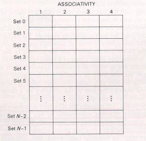
fig.2 The logical organization of a
four-way set-associate cache
Fig.2 shows a conceptual implementation of a cache memory. This
system is called set associative because the cache is partitioned into
distinct sets of blocks, ad each set contains a small fixed number of
blocks. The sets are represented by the rows in the figure. In this
case, the cache has N sets, and each set contains four blocks. When an
access occurs to this cache, the cache controller does not search the
entire cache looking for a match. Instead, the controller maps the
address to a particular set of the cache and searches only the set for a
match.
If the block is in the cache, it is guaranteed to be in the set that
is searched. Hence, if the block is not in that set, the block is not
present in the cache, and the cache controller searches no further.
Because the search is conducted over four blocks, the cache is said to
be four-way set associative or, equivalently, to have an associativity
of four.
Fig.2 is only one example, there are various ways that a cache can be
arranged internally to store the cached data. In all cases, the
processor reference the cache with the main memory address of the data
it wants. Hence each cache organization must use this address to find
the data in the cache if it is stored there, or to indicate to the
processor when a miss has occurred. The problem of mapping the
information held in the main memory into the cache must be totally
implemented in hardware to achieve improvements in the system operation.
Various strategies are possible.
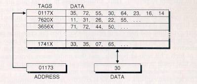
- Fully associative mapping
Perhaps the most obvious way of relating cached data to the main
memory address is to store both memory address and data together in
the cache. This the fully associative mapping approach. A fully
associative cache requires the cache to be composed of associative
memory holding both the memory address and the data for each cached
line. The incoming memory address is simultaneously compared with all
stored addresses using the internal logic of the associative memory,
as shown in Fig.3. If a match is fund, the corresponding data is read
out. Single words form anywhere within the main memory could be held
in the cache, if the associative part of the cache is capable of
holding a full address
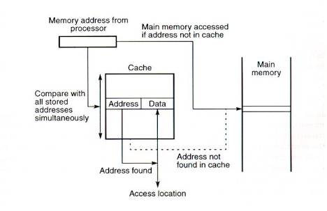
Fig.3 Cache with fully associative
mapping
In all organizations, the data can be more than one word, i.e., a
block of consecutive locations to take advantage of spatial locality.
In Fig.4 aline constitutes four words, each word being 4 bytes. The
least significant part of the address selects the particular byte, the
next part selects the word, and the remaining bits form the address
compared to the address in the cache. The whole line can be
transferred to and from the cache in one transaction if there are
sufficient data paths between the main memory and the cache. With only
one data word path, the words of the line have to be transferred in
separate transactions.
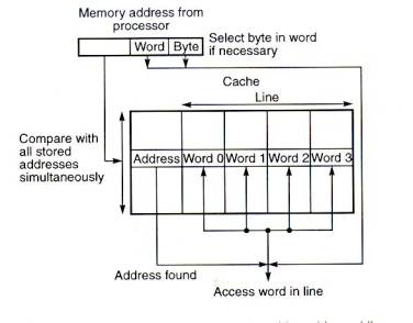
Fig.5 Fully associative mapped cache
with multi-word lines
The fully associate mapping cache gives the greatest flexibility of
holding combinations of blocks in the cache and minimum conflict for a
given sized cache, but is also the most expensive, due to the cost of
the associative memory. It requires a replacement algorithm to select
a block to remove upon a miss and the algorithm must be implemented in
hardware to maintain a high speed of operation. The fully associative
cache can only be formed economically with a moderate size capacity.
Microprocessors with small internal caches often employ the fully
associative mechanism.
The fully associative cache is expensive to implement because of
requiring a comparator with each cache location, effectively a special
type of memory. In direct mapping, the cache consists of normal
high speed random access memory, and each location in the cache holds
the data, at an address in the cache given by the lower significant
bits of the main memory address. This enables the block to be selected
directly from the lower significant bits of the memory address. The
remaining higher significant bits of the address are stored in the
cache with the data to complete the identification of the cached data.
Consider the example shown in Fig.5. The address from the processor
is divided into tow fields, a tag and an index. The tag consists of
the higher significant bits of the address, which are stored with the
data. The index is the lower significant bits of the address used to
address the cache.
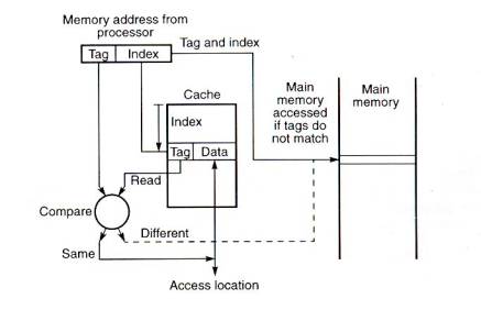
Fig.5 Cache with direct mapping
When the memory is referenced, the index is first used to access a
word in the cache. Then the tag stored in the accessed word is read
and compared with the tag in the address. If the two tags are the
same, indicating that the word is the one required, access is made to
the addressed cache word. However, if the tags are not the same,
indicating that the required word is not in the cache, reference is
made to the main memory to find it. For a memory read operation, the
word is then transferred into the cache where it is accessed. It is
possible to pass the information to the cache and the processor
simultaneously, i.e., to read-through the cache, on a miss. The cache
location is altered for a write operation. The main memory may be
altered at the same time (write-through) or later.
Fig.6. shows the direct mapped cache with a line consisting of more
than one word. The main memory address is composed of a tag, an index,
and a word within a line. All the words within a line in the cache
have the same stored tag. The index part to the address is used to
access the cache and the stored tag is compared with required tag
address. For a read operation, if the tags are the same the word
within the block is selected for transfer to the processor. If the
tags are not the same, the block containing the required word is first
transferred to the cache.
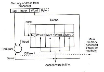
Fig.6 Direct mapped cache with a
multi-word block
In direct mapping, the corresponding blocks with the same index in
the main memory will map into the same block in the cache, and hence
only blocks with different indices can be in the cache at the same
time. A replacement algorithm is unnecessary, since there is only one
allowable location for each incoming block. Efficient replacement
relies on the low probability of lines with the same index being
required. However there are such occurrences, for example, when two
data vectors are stored starting at the same index and pairs of
elements need to processed together. To gain the greatest performance,
data arrays and vectors need to be stored in a manner which minimizes
the conflicts in processing pairs of elements. Fig.6 shows the lower
bits of the processor address used to address the cache location
directly. It is possible to introduce a mapping function between the
address index and the cache index so that they are not the same.
In the direct scheme, all words stored in the cache must have
different indices. The tags may be the same or different. In the fully
associative scheme, blocks can displace any other block and can be
placed anywhere, but the cost of the fully associative memories
operate relatively slowly.
Set-associative mapping allows a limited number of blocks,
with the same index and different tags, in the cache and can therefore
be considered as a compromise between a fully associative cache and a
direct mapped cache. The organization is shown in Fig.7. The cache is
divided into "sets" of blocks. A four-way set associative
cache would have four blocks in each set. The number of blocks in a
set is know as the associativity or set size. Each block in
each set has a stored tag which, together with the index, completes
the identification of the block. First, the index of the address from
the processor is used to access the set. Then, comparators are used to
compare all tags of the selected set with the incoming tag. If a match
is found, the corresponding location is accessed, other wise, as
before, an access to the main memory is made.
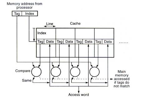
Fig.7 Cache with set-associative
mapping
The tag address bits are always chosen to be the most significant
bits of the full address, the block address bits are the next
significant bits and the word/byte address bits form the least
significant bits as this spreads out consecutive man memory blocks
throughout consecutive sets in the cache. This addressing format is
known as bit selection and is used by all known systems. In a
set-associative cache it would be possible to have the set address
bits as the most significant bits of the address and the block address
bits as the next significant, with the word within the block as the
least significant bits, or with the block address bits as the least
significant bits and the word within the block as the middle bits.
Notice that the association between the stored tags and the
incoming tag is done using comparators and can be shared for each
associative search, and all the information, tags and data, can be
stored in ordinary random access memory. The number of comparators
required in the set-associative cache is given by the number of blocks
in a set, not the number of blocks in all, as in a fully associative
memory. The set can be selected quickly and all the blocks of the set
can be read out simultaneously with the tags before waiting for the
tag comparisons to be made. After a tag has been identified, the
corresponding block can be selected.
The replacement algorithm for set-associative mapping need only
consider the lines in one set, as the choice of set is predetermined
by the index in the address. Hence, with two blocks in each set, for
example, only one additional bit is necessary in each set to identify
the block to replace.
In sector mapping, the main memory and the cache are both divided
into sectors; each sector is composed of a number of blocks. Any
sector in the main memory can map into any sector in the cache and a
tag is stored with each sector in the cache to identify the main
memory sector address. However, a complete sector is not transferred
to the cache or back to the main memory as one unit. Instead,
individual blocks are transferred as required. On cache sector miss,
the required block of the sector is transferred into a specific
location within one sector. The sector location in the cache is
selected and all the other existing blocks in the sector in the cache
are from a previous sector.
Sector mapping might be regarded as a fully associative mapping
scheme with valid bits, as in some microprocessor caches. Each block
in the fully associative mapped cache corresponds to a sector, and
each byte corresponds to a "sector block".
3. Cache Performance
The performance of a cache can be quantified in terms of the hit and
miss rates, the cost of a hit, and the miss penalty, where a cache hit
is a memory access that finds data in the cache and a cache miss is one
that does not.
When reading, the cost of a cache hit is roughly the time to access
an entry in the cache. The miss penalty is the additional cost of
replacing a cache line with one containing the desired data.
| (Access time) |
= (hit cost) + (miss rate)*(miss penalty) |
|
=(Fast memory access time) + (miss rate)*(slow
memory access time) |
Note that the approximation is an underestimate - control costs have
been left out. Also note that only one word is being loaded from the
faster memory while a whole cache block's worth of data is being loaded
from the slower memory.
Since the speeds of the actual memory used will be improving
``independently'', most effort in cache design is spent on fast control
and decreasing the miss rates. We can classify misses into three
categories, compulsory misses, capacity misses and conflict misses.
Compulsory misses are when data is loaded into the cache for the first
time (e.g. program startup) and are unavoidable. Capacity misses are
when data is reloaded because the cache is not large enough to hold all
the data no matter how we organize the data (i.e. even if we changed the
hash function and made it omniscient). All other misses are conflict
misses - there is theoretically enough space in the cache to avoid the
miss but our fast hash function caused a miss anyway.
4. Fetch and write mechanism
We can identify three strategies for fetching bytes or blocks from
the main memory to the cache, namely:
- Demand fetch
- Which is the fetching a block when it is needed and is not
already in the cache, i.e. to fetch the required block on a
miss. This strategy is the simplest and requires no additional
hardware or tags in the cache recording the references, except
to identify the block in the cache to be replaced.
- Prefetch
- Which is fetching blocks before they are requested. A simple
prefetch strategy is to prefetch the (i+1)th block when
the ith block is initially referenced on the
expectation that it is likely to be needed if the ith
block is needed. On the simple prefetch strategy, not all
first references will induce a miss, as some will be to
prefetched blocks.
- Selective fetch
- Which is the policy of not always fetching blocks, dependent
upon some defined criterion, and in these cases using the main
memory rather than the cache to hold the information. For
example, shared writable data might be easier to maintain if
it is always kept in the main memory and not passed to a cache
for access, especially in multi-processor systems. Cache
systems need to be designed so that the processor can access
the main memory directly and bypass the cache. Individual
locations could be tagged as non-cacheable.
- Instruction and data caches
The basic stored program computer provides for one main memory for
holding both program instructions and program data. The cache can be
organized in the same fashion, with the cache holding both program
instructions and data. This is called a unified cache. We also can
separate the cache into two parts: data cache and instruction (code)
cache. The general arrangement of separate caches is shown in fig.8.
Often the cache will be integrated inside the processor chip.
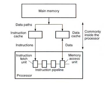
Fig.8 Separate instruction and data
caches
As reading the required word in the cache does not affect the cache
contents, there can be no discrepancy between the cache word and the
copy held in the main memory after a memory read instruction. However,
in general, writing can occur to cache words and it is possible that
the cache word and copy held in the main memory may be different. It
is necessary to keep the cache and the main memory copy identical if
input/output transfers operate on the main memory contents, or if
multiple processors operate on the main memory, as in a shared memory
multiple processor system.
If we ignore the overhead of maintaining consistency and the time
for writing data back to the main memory, then the average access time
is given by the previous equation, i.e. teff = tcache +
( 1 - h ) tmain , assuming that all accesses are first made
to the cache. The average access time including write operations will
add additional time to this equation that will depend upon the
mechanism used to maintain data consistency.
There are two principal alternative mechanisms to update the main
memory, namely the write-through mechanism and the write-back
mechanism.
In the write-though mechanism, every write operation to the cache
is repeated to the main memory, normally at the same time. The
additional write operation to the main memory will, of course, take
much longer than to the cache and will dominate the access time for
write operations. The average access time of write-through with
transfers from main memory to the cache on all misses (read and write)
is given by:
|
ta |
= tcache + ( 1 - h ) ttrans
+ w(tmain - tcache) |
|
= (1 - w) tcache + (1 - h) ttrans
+ wtmain |
|
|
|
Where ttrans |
= time to transfer block to cache, assuming
the whole block must be transferred together |
|
W |
= fraction of write references.
|
The term (tmain - tcache) is the additional
time to write the word to main memory whether a hit or a miss has
occurred, given that both cache and main memory write operation occur
simultaneously but the main memory write operation must complete
before any subsequent cache read/write operation can be proceed. If
the size of the block matches the external data path size, a whole
block can be transferred in one transaction and ttrans = tmain.
On a cache miss, a block could be transferred from the main memory
to the cache whether the miss was caused by a write or by a read
operation. The term allocate on write is used to describe a
policy of bringing a word/block from the main memory into the cache
for a write operation. In write-through, fetch on write transfers are
often not done on a miss, i.e., a Non- allocate on write policy.
The information will be written back to the main memory but not kept
in the cache.
The write-through scheme can be enhanced by incorporating buffers,
as shown in Fig.9, to hold information to be written back to the main
memory, freeing the cache for subsequent accesses.
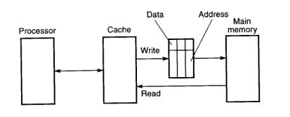
Fig.9 Cache with write buffer
For write-through, each item to be written back to the main memory
is held in a buffer together with the corresponding main memory
address if the transfer cannot be made immediately.
Immediate writing to main memory when new values are generated
ensures that the most recent values are held in the main memory and
hence that any device or processor accessing the main memory should
obtain the most recent values immediately, thus avoiding the need for
complicated consistency mechanisms. There will be latency before the
main memory has been updated, and the cache and main memory values are
not consistent during this period.
In the write-back mechanism, the write operation to the main memory
is only done at block replacement time. At this time, the block
displaced by the incoming block might be written back to the main
memory irrespective of whether the block has been altered. The policy
is known as simple write-back, and leads to an average access time of:
ta = tcache + ( 1 - h ) ttrans
+ (1 - h) ttrans
Where one (1 - h) ttrans term is due to fetching a block
from memory and the other (1 - h) ttrans term is due to
writing back a block. Write-back normally handles write misses as
allocate on write, as opposed to write-through, which often handles
write misses as Non-allocate on write.
The write-back mechanism usually only writes back lines that
have been altered. To implement this policy, a 1-bit tag is associated
with each cache line and is set whenever the block is altered. At
replacement time, the tags are examined to determine whether it is
necessary to write the block back to the main memory. The average
access time now becomes:
ta = tcache + ( 1 - h ) ttrans
+ wb(1 - h) ttrans
where wb is the probability that a block
has been altered (fraction of blocks altered). The probability that a
block has been altered could be as high as the probability of write
references, w, but is likely to be much less, as more than one write
reference to the same block is likely and some references to the same
byte/word within the block are likely. However, under this policy the
complete block is written back, even if only one word in the block has
been altered, and thus the policy results in more traffic than is
necessary, especially for memory data paths narrower than a line, but
still there is usually less memory traffic than write-through, which
causes every alteration to be recorded in the main memory. The
write-back scheme can also be enhanced by incorporating buffers to
hold information to be written back to the main memory, just as is
possible and normally done with write-through.
5. Replacement policy
When the required word of a block is not held in the cache, we have
seen that it is necessary to transfer the block from the main memory
into the cache, displacing an existing block if the cache is full.
Except for direct mapping, which does not allow a replacement algorithm,
the existing block in the cache is chosen by a replacement algorithm.
The replacement mechanism must be implemented totally in hardware,
preferably such that the selection can be made completely during the
main memory cycle for fetching the new block. Ideally, the block
replaced will not be needed again in the future. However, such future
events cannot be known and a decision has to be made based upon facts
that are known at the time.
- Random replacement algorithm
Perhaps the easiest replacement algorithm to implement is a
pseudo-random replacement algorithm. A true random replacement
algorithm would select a block to replace in a totally random order,
with no regard to memory references or previous selections; practical
random replacement algorithms can approximate this algorithm in one of
several ways. For example, one counter for the whole cache could be
incremented at intervals (for example after each clock cycle, or after
each reference, irrespective of whether it is a hit or a miss). The
value held in the counter identifies the block in the cache ( if fully
associative) or the block in the set if it is a set-associative cache.
The counter should have sufficient bits to identify any block. For a
fully associative cache, an n-bit counter is necessary if there are 2n
words in the cache. For a four-way set-associative cache, one
2-bit counter would be sufficient, together with logic to increment
the counter.
- First-in first-out replacement algorithm
The first-in first-out replacement algorithm removes the block that
has been in the cache for the longest time. The first-in first-out
algorithm would naturally be implemented with a first-in first-out
queue of block address, but can be more easily implemented with
counters, only one counter for a fully associative cache or one
counter for each set in a set-associative cache, each with a
sufficient number of bits to identify the block.
- Least recently used algorithm for a cache
In the least recently used (LRU) algorithm, the block which
has not been referenced for the longest time is removed from the
cache. Only those blocks in the cache are considered. The word
"recently" comes about because the block is not the least
used, as this is likely to be back in memory. It is the least used of
those blocks in the cache, and all of those are likely to have been
recently used otherwise they would not be in the cache. The least
recently used (LRU) algorithm is popular for cache systems and can be
implemented fully when the number of blocks involved is small. There
are several ways the algorithm can be implemented in hardware for a
cache, these include:
1) Counters
In the counter implementation, a counter is associated with each
block. A simple implementation would be to increment each counter at
regular intervals and to reset a counter when the associated line had
been referenced. Hence the value in each counter would indicate the
age of a block since last referenced. The block with the largest age
would be replaced at replacement time.
2) Register stack
In the register stack implementation, a set of n-bit registers is
formed, one for each block in the set to be considered. The most
recently used block is recorded at the "top" of the stack
and the least recently used block at the bottom. Actually, the set of
registers does not form a conventional stack, as both ends and
internal values are accessible. The value held in one register is
passed to the next register under certain conditions. When a block is
referenced, starting at the top of the stack, starting at the top of
the stack, the values held in the registers are shifted one place
towards the bottom of the stack until a register is found to hold the
same value as the incoming block identification. Subsequent registers
are not shifted. The top register is loaded with the incoming block
identification. This has the effect of moving the contents of the
register holding the incoming block number to the top of the stack.
This logic is fairly substantial and slow, and not really a practical
solution.
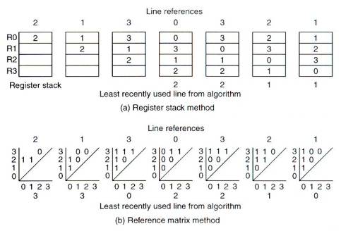
Fig.10 Least recently used replacement
algorithm implementation
3) Reference matrix
The reference matrix method centers around a matrix of status bits.
There is more than one version of the method. In one version (Smith,
1982), the upper triangular matrix of a B X B matrix is formed without
the diagonal, if there are B blocks to consider. The triangular matrix
has (B * (B - 1))/2 bits. When the ith block is referenced, all the
bits in the ith row of the matrix are set to 1 and then all the bits
in the ith column are set to 0. The least recently used block is one
which has all 0's in its row and all 1's in its column, which can be
detected easily by logic. The method is demonstrated in Fig.10 for B =
4 and the reference sequence 2, 1, 3, 0, 3, 2, 1,
, together with
the values that would be obtained using a register stack.
4) Approximate methods.
When the number of blocks to consider increases above about four to
eight, approximate methods are necessary for the LRU algorithm. Fig.11
shows a two-stage approximation method with eight blocks, which is
applicable to any replacement algorithm. The eight blocks in Fig.11
are divided into four pairs, and each pair has one status bit to
indicate the most/least recently used block in the pair (simply set or
reset by reference to each block). The least recently used replacement
algorithm now only considers the four pairs. Six status bits are
necessary (using the reference matrix) to identify the least recently
used pair which, together with the status bit of the pair, identifies
the least recently used block of a pair.
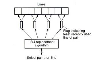
Fig.11 Two-stage replacement algorithm
The method can be extended to further levels. For example, sixteen
blocks can be divided into four groups, each group having two pairs.
One status bit can be associated with each pair, identifying the block
in the pair, and another with each group, identifying the group in a
pair of groups. A true least recently used algorithm is applied to the
groups. In fact, the scheme could be taken to its logical conclusion
of extending to a full binary tree. Fig.12 gives an example. Here,
there are four blocks in a set. One status bit, B0,
specifies which half o the blocks are most/least recently used. Two
more bits, B1 and B2, specify which block of
pairs is most/least recently used. Every time a cache block is
referenced (or loaded on a miss), the status bits are updated. For
example, if block L2 is referenced, B2 is set to
a 0 to indicate that L2 is the most recently used of the
pair L2 and L3. B0 is set to a 1 to
indicate that L2/L3 is the most recently used of
the four blocks, L0, L1, L2 and L3.
To identify the line to replace on a miss, the status bits are
examined. If B0 = 0, then the block is either L0
or L1. If then B1 = 0, it is L0.
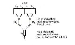
Fig.12 Replacement algorithm using a
tree selection
6. Second-level caches
When the cache is integrated into the processor, it will be
impossible to increase its size should the performance not be
sufficient. In any case, increasing the size of the cache may create a
slower cache. As an alternative, which has become very popular, a second
larger cache can be introduced between the first cache and the main
memory as shown in Fig.13. This "second-level" cache is
sometimes called a secondary cache.
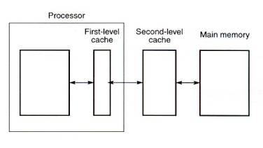
Fig.13 Two-level caches
On a memory reference, the processor will access the first-level
cache. If the information is not found there (a first-level cache miss
occurs), the second-level cache will be accessed. If it is not in the
second cache (a second-level cache miss occurs), then the main memory
must be accessed. Memory locations will be transferred to the
second-level cache and then to the first-level cache, so that two copies
of a memory location will exist in the cache system at least initially,
i.e., locations cached in the second-level cache also exist in the
first-level cache. This is known as the Principle of Inclusion.
(Of course the copies of locations in the second-level cache will never
be needed as they will be found in the first-level cache.) Whether this
continues will depend upon the replacement and write policies. The
replacement policy practiced in both caches would normally be the least
recently used algorithm. Normally write-through will be practiced
between the caches, which will maintain duplicate copies. The block size
of the second-level cache will be at least the same if not larger than
the block size of the first-level cache, because otherwise on a
first-level cache miss, more than one second-level cache line would need
to be transferred into the first-level cache block.