

Introduction to MIMD Architectures
MIMD (Multiple Instruction stream, Multiple Data stream) computer system has a number of independent processors operate upon separate data concurrently. Hence each processor has its own program memory or has access to program memory. Similarly, each processor has its own data memory or access to data memory. Clearly there needs to be a mechanism to load the program and data memories and a mechanism for passing information between processors as they work on some problem. MIMD has clearly emerges the architecture of choice for general-purpose mutiprocessors. MIMD machines offer flexibility. With the correct hardware and software support, MIMDs can function as single user machines focusing on high performance for one application, as multiprogrammed machines running many tasks simultaneously, or as some combination of these functions. There are two types of MIMD architectures: distributed memory MIMD architecture, and shared memory MIMD architecture.

Distributed Memory MIMD Architectures
Without accessibility to shared memory architectures, it is not possible to obtain memory access of a remote block in a multicomputer. Rather than having a processor being allocated to different process or having a processor continue with other computations (in other words stall), Distributed MIMD architectures are used. Thus, the main point of this architectural design is to develop a message passing parallel computer system organized such that the processor time spent in communication within the network is reduced to a minimum.
Within a multicomputer, there are a large number of nodes and a communication network linking these nodes together. Inside each node, there are three important elements that do have tasks related to message passing :
This component is responsible for organizing communication among the multicomputer nodes, "packetizing" a message as a chunk of memory in the on the giving end, and "depacketizing" the same message for the receiving node.
The routers main task is to transmit the message from one node to the next and assist the communication processor in organizing the communication of the message in through the network of nodes.
The development of each of the above three elements took place progressively, as hardware became more and more complex and useful. First came the Generation I computers, in which messages were passed through direct links between nodes, but there were not any communication processors or routers. Then Generation II multicomputers came along with independent switch units that were separate from the processor, and finally in the Generation III multicomputer, all three components exist.
One method of classifying a multicomputers scheme of message transmission is its interconnection network topology, which in plain English means how the nodes are geometrically arranged as a network. There is great value in this information. The idea behind it is related to the notion in computer science known as the Traveling Salesman problem, the Shortest Path Algorithm from point A to point B(or in this case node A to node B) is directly linked to the shape that the nodes generate when linked together. Interconnection network topology has a great influence on message transmission.
Background Information On Interconnection Topologies
With a geometrically arranged network,(eg star, hypercube) there are several "tradeoffs" associated with the given "designs" ability to transmit messages as quickly as possible:
Interconnection Topology Types
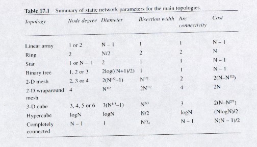
Below is the picture for the three categories of interconnection topologies (one dimensional, two dimensional, and three dimensional) and the designs that fall under each one. Along with this, there is a table comparing each topology based on the tradeoffs listed above

B. Switching
A second method of comparing multicomputer schemes of message transmission is something called switching which basically means the method of moving messages from input to output buffers. The "buffer" is the location where the message, or a part of the message is to be stored.
Three main types of switching need to be discussed:
This mechanism of message storing and movement can be though as the way the mail service, and is probably is just as slow A message is split into "packets" that can be stored in the buffer, contained within each intermediate node(the intermediate node between the source node sending the message and the correct receiver of the message) A "packet" usually will contain a header and some data. The header portion works like a tag telling the switching unit which node to forward the data to, in order to reach the destination node.
Network Latency = P/(B*D)
where P is the packet length, B is the channel bandwidth and D is the number of nodes within the network.
Some drawbacks of packet switching include a higher network latency time in message delivery due to the above equations dependency on the packet length and the packet switching mechanism tends to consume a whole lot of memory for the buffering of the "packets".
The circuit switching method is like a telephone system in which the message passage path develops from source node to destination node as the message travels through its path. The three phases of this type of switching scheme are the circuit establishment phase. This term is exactly what it sounds like, setting up of a circuit from source node to destination node as you move from node to node. In this scheme, the entire message can be sent at once through a special probe. There is one rule that is followed as the message is being passed and it is used whenever more than one message is being transmitted at a given time. In this case, a collision may result between the two messages if there is an intermediate node that both messages need to pass through to reach their respective destinations. However circuit switching does not allow more than one message to pass through a channel at a time, so the message that got their last needs to wait.
Here the Network Latency equation(NL) is
NL = (P/B)*D + M/B
P = packet length, B= channel bandwidth, D is number of nodes in the network, and M stands for the message length
The transmission phase transmits the message to the next phase and during the termination phase the circuitry is broken once the destination is reached
The major advantage of circuit switching is that the elimination of buffering reduces memory consumption.
In this scheme, the message is initially divided into small subunits, a set of flow control digits. If the message s traveling and reaches a busy channel, the flits, or portions of the message are buffered at the respective intermediate node where the channel was unavailable.
Here, the Network Latency is computed by the following formula
NL = HF/B * D + (M/B)
where the B= channel bandwidth, D = number of nodes in the network, M is the message length and HF is the length of the header flit
This method of switching is similar to the Virtual cut Through mechanism, where the difference being is that the given flit size that is buffered fits into the buffer at the intermediate node perfectly. Also, packet replication is now possible, meaning that copies of the flits can be sent out through several output channels(multi-directional). Lastly, wormhole routing introduces us to the concept of virtual channels, where multiple messages can now use the same channel to transmit their respective messages.
These virtual channels have several advantages, one of them being that their is an increase in network throughput by reducing the time nodes spend within the physical channels they pass through, guarantee a communication bandwidth to system related functions, such as debugging, and are used to avoid deadlock avoidance, a concept explained in the next paragraph.
In a deadlock, a subset of the messages(the flits, I believe) are all blocked at once and are awaiting a free buffer to be released by a message that follows it.This problem can be resolved by rerouting the message from the node where you are as occurs in the wormhole routing solution, or move the flit all the way back to the source node moving in another path towards the destination, or the last solution, the virtual channel.
C.Routing
Routing is the determination of a path, whether it is the shortest or the longest or somewhere in between, from the source to the destination node. Two broad categories of routing exist--- deterministic and adaptive. In deterministic routing, the path is determined by the source and destination nodes and in adaptive routing the intermediate nodes can "see" a blocked channel on their way to their destination and can reroute to a new path. This works similar to the way people normally alter their paths of traveling when hearing about the accident on I -495.
Deterministic routing has two more sub-categories that fall within it. One of them is named is source routing, a method in which the source node determines the routing path to the destination. The other method, distributed routing, considers all intermediate nodes and the source node in determining the best path towards the destination, avoiding blocked channels.
I. THE TYPES OF DETERMINISTIC ROUTING
Source Routing Means----
Street Sign Routing
Street Sign routing requires that the message header carries the entire path information.
At each turn of the node, the path towards the destination has been predetermined. However each message header also has the capability to choose a default direction in which case an intermediate nodes channel is in use. It does this by comparing the nodes address to see if a miss occurred.
Distributed Routing Schemes-----
Dimension Ordered Routing
Dimension ordered routing is best explained through a diagram provided in Figure 17.14 and is a routing method in which a message moves along a "dimension" until it reaches the a certain coordinate and moves through another dimension. This scheme only works if the source node and destination node lie along different dimensions.

Table Lookup Routing
In this type of routing, a table is formulated so that any given node can go where to forward its message. Of course, this style of routing eats away at a lot of hardware, but is good in software usage. This is because a very huge lookup table will require a very big chip area.
II. THE TYPES OF ADAPTIVE ROUTING
There are two general categories of adaptive routing. One is referred to as profitable routing in which the only channels that are taken as the message travels from source node to destination node are the ones that always move closer to the destination. Profitable routing ensures a minimum path length and tends to minimize the possibility of a deadlock, discussed earlier. The other category of adaptive routing misrouting protocols is more flexible and allows for usage of the most cost efficient means of getting the message to its destination whenever it is deemed appropriate in the network "situation". Also, adaptive routing types may vary on whether the algorithm they utilize allows for backtracking the message to get out of a nasty situation. The header of the message must carry a tag within it so that it will not continue looping the same path if backtracking is permitted. If the header becomes very large because this, time is lost during the search. Lastly, any given "protocol" in adaptive routing can either be partially adaptive, meaning it can choose from a part of the channels to move through or completely adaptive, in which case it moves to any channel it wants.
FINE GRAIN SYSTEMS described through the following example
Message Driven Processor and the J-Machine
The creation of the J-machine at MIT fulfilled two important goals: it supported many parallel programming models , such as the data flow model and actor based object oriented model through the MDP (Message Driven Processor) chip, and showed that combing many MDP chips into several nodes can produce what is called a fine grain system.
The MDP has combined a processor, memory unit, and communication unit into a single chip. The node connecting method chosen is a be a 3D mesh, using a deterministic and wormhole routing scheme.

The above diagram is the design layout of a typical MDP chip with six bi-directional bit parallel channels. There are six network ports corresponding to the six directions possible in a 3-D grid(+X, -X, +Y, -Y, +Z, -Z). Here, messages are divided into flits, corresponding to the addresses X, Y, and Z. If a message comes to a node in dimension D, the address at the node
is compared with the flit. If there is a match, all the flits behind the match "move one over" in the direction of the destination node. (Recall that wormhole routing is in use) By the way it is the router unit that makes this determination, and in the above diagram there are three such router units. (for each of the three dimensions)
If a message is blocked, it remains compressed within the router unit and uses a bit flit buffer. Once the path clears, the message becomes uncompressed and can now move forward. Higher priority messages are transferred more quickly, by using separate virtual channels to arrive to their destination faster.
The MDP system also contains a network input and output unit. The output unit is used to store an eight word buffer every time flit of the message is moved from one node to the next. The input buffer is a collection unit for the flits message portion.
Architecture of Message Driven Processor
The MDPs value in the fine grain system has three aspects to it: it reduced overhead time for receiving a message, it reduced context switch time, and provided hardware support for object oriented programming.
There are three "levels" of execution based on "need" for the message to be sent over from least quickly needed to most--- background priority, priority 1, and priority 2.
Type checking of the message is also possible in the MDP system through a 4 bit tag. Tags named Cfut and Fut are used for synchronization checks, ensuring flits are passed correctly.
The network instructions here include SEND, SENDE, SEND2, SEND2E and are used to send messages between processors.
Some typical commands include:
SEND R0,1; send destination address
SEND2 R1, R2.1 ; header and receiver
SEND2E R3[2,A3],1 ; two words sent and end of message
Instruction one sends the X,Y, and Z coordinates of the destination processor to R0. The second instruction sets R1(register 1) and R2(register 2) for transmission. Finally instruction 3 combines a word from memory with the end of the message to let the J-Machine know the message has finished being sent.
Together, the message unit (MU ) and instruction unit (IU) determine which message
has the highest priority and allows that one to be passed first by a suspending the former instruction currently in action. Messages can be stored in queue fashion, thus achieving the well known FIFO property.
The J-Machine has several flaws within it. It has access to too few register sets R0-R3 and makes many memory reference calls and some messages are locked out for a long time if they end up at the back of the queue. The external bandwidth of the MDP structure is three times smaller than the one found in many network designs. Along with this, the inability to use floating point in the J-Machine is a big down side, so we turn to
Medium Grain Systems
The medium grain system is based on the Transputer, a complete microcomputer that contains a central chip within it, a floating point processor, static RAM, interface for external memory, and several communication links into a given chip. Transputers are used to develop a synchronous parallel programming model.
Two generations of Transputers have been developed in the passed few decades. The first generation was mainly used for applications involving signal processing and were small systems with quick communication links. Its main advantage was that it eliminated usage of a multi-bus system, yet was not much quicker in terms of computations. The newer generation incorporates a C104 router chip and a better processing node structure.
THE SECOND GENERATION TRANSPUTER T9000
The major features of Transputer9000 include a 32 bit integer processor, a 64 bit floating point unit, and 16KB of CPU cache, four serial communication links, virtual channel processor, and a programmable memory interface. (PMI) An internal crossbar connects the CPU cache, PMI, and virtual channel processor these to the four banks of the main cache.
Process management in Transputers
This particular Transputer has a small register set(6 of them) yet it still maintains fast contexting switch. Register A is the stack top. Register four, W, points to the workspace area. The fifth register acts as a PC(program counter) and register six is responsible for "elaborating" operands.
Processes can be in one of three states: Active, Ready, and Inactive. In the active stage, the Program Counter is loaded into the register PC and the workspace gets pointed to W by W. In the ready stage, the PC is stored in its workspace register, W, and the also stores two Ready lists(one for high priority and one for low priority messages). The Ready list, like a normal queue, has a front and a back "pointer" for its head and its tail.
The last stage in a transputers processes is the inactive stage, and is awaiting one of the following situations to take place: completed execution of channel operations, the execution to reach a specified time, or getting access to an open semaphore.
In order to switch from one process to another, the following steps are required:
Channel Communication in Transputers
Communication between a receiver and a sender of a message is always an asynchronous process. Only after the "partner process" completes its usage of a channel can a sender transmit its message. Prior to channel usage of a message, each channel in the network is set to Not Process. When a channel needs to be used, the data length of the message, its pointer, and the channel location itself are all stored in the register stack. The Register named A defines the length of the message, Register C contains the memory address where the message is actually stored and Register B tells what channel will be in use next. Now, by looking in Register B, the availability of the next process becomes easier to attain as it is transferred from process P( i ) to P( j ).
Communication Between Neighboring Transputers
Each Transputer has something within it called an OS -Link, and is used to chain together many Transputers. The data between the two Transputers is sent byte by byte The OS link has a relatively slow speed of operation compared to other hardware available on the market, but is still cheaper to buy if costs are a concern. However, problems may result with the OS link if the process mapping strategy for linking the Transputers becomes complex

Due to this a new concept, known as virtual links was developed. Virtual links are built off the concepts of bit level protocols, token level protocols, packet level protocols, and message passing protocols.
Bit level protocols contain within them DS links rather than OS Links and have four wires, a data strobe line going in both the input and output directions. (In bit level protocol, transmission of messages is faster than before, but the receiving rate of messages is still somewhat slow.
Token level protocol s are used prevent the process sending the message from overusing the entire input buffer for message transmission. Here, the receiver of a message lets the sender of the process know that it is ok to send forth more of the message to reach the destination. Some of the commands associated with this include:
00 Flow control token(FCT)
01 End of packet(EOP)
10 End of message(EOM)
11 Escape Token(ESC)
Packet Level Protocol
Here packetizing of messages takes place rather than usage of the flit method, but is essentially the same concept as the token level protocol
Message Passing Protocol
Here, a "virtual link" list is used that is similar to the idea of a ready list. Whenever a message is sent out or received, the VCP unit of the T9000 "deschedules" the message currently being worked on. The identifier of the new process is also saved and execution of it begins. Once this is complete the process that had been waitlisted now continues at the command of the VCP unit.In this way, the VCP lets through messages of higher priority.
Communication Between Remote Transputers
In a remote system, the packets of messages to be distributed use the header in the same way any longer . Instead, a C104 chip is used to develop a different routing switch scheme. The C104 chip, FIGURE 17.25 is shown below.

The C104 chip uses a deterministic, distributed, minimal routing protocol called interval labeling. Each interval for a given router is non overlapping. An intervals destination address determines where the message packet will be sent. The routing decision unit for each packet is named the interval selector unit. It has a thirty-five limit and base comparator within it. More than one interval can be assigned to it. When a packet arrives to the C104 router its header is sent to the interval selector unit when the crossbar switch matches the message headers data. After this, all the tokens can pass through until the terminating token reaches its destination.
T9000 based machines
The Parasytec GC
Characteristics:
1)3D interconnection topology
2) connects up to 16, 384 nodes

I. Coarse Grain Multicomputers
One group of Coarse Grain Multicomputers is referred to as homogeneous multicomputers and still contain the three components necessary for parallel message-passing, a computation processor, a communication processor and a router. The are attributed with a RISC superscalar architecture and effectively utilize many MFLOPS per a node so that the communication processor can support the computation processor in maintaining a lower level of communication. In a different coarse grain multicomputer type, A router is sometimes replaced with a custom designed communication switch Some examples of this include the Paragon, the CS-2 and the Manna.In a third architectural design of coarse grain multicomputers, custom designed communication processors are used to obtain a high performance level. This characteristic is also attributed to the CS-2 which also contains vector processing units for each node The last type of coarse grain multicomputers is known as hybrid multicomputers, and has different processor types used in computation and communication processes. Some examples here include the revised Parasytec GC, the PowerPlus, and the IBM SP1 and SP2.
The major topology designs that are mainly used on coarse grain systems include the following: mesh, cube , and fat tree due to their lower implementation costs and has better than average scalability.
A. Homogeneous Architectures
Intel Paragon
The Intel paragon was based on the hypercube topology. The Paragon contains three node types : compute nodes, service nodes, and input/output nodes. The compute nodes sole responsibility is computations and are considered multiprocessor nodes, in contrast to the other two node types, thought of as general purpose nodes. Each general purpose node contains an expansion port for addition of an input and output interface . The input/output nodes themselves serve to support input/output connectivity and the service nodes are involved in providing interactive use for many users.
The Multi Processor (MP) node in this architecture is a small sized shared memory multiprocessor . The nodes memory is shared in a four way system of processors and each has a 25 KB second level cache. The MP node also has a i860 chip used as a message processor.
The message passing process is started at the application processor but is performed mostly by the message processor. The software used in message passing is executed from the internal cache just discussed.
The architecture also consists of a Message routing unit known as the Mesh Router Controller(MRC) formulated through a connected 2D mesh. The MRC allows message passing at the high speed rate of 200 Mbyte/second . The MRC is made up of a 5X 5 crossbar switch with flit buffers and many input controllers. Along with this, two block transmission engines are included to support communication in a node. The Network Interface Controller(NIC) provides a pipelined interface between the MRC of the node and the nodes memory.
B. Hybrid Architectures
Hybrid architectures use high-performance commodity microprocessors for computations. The communication processor is typically a Transputer and the internal hardware supports intensive computations. In this case first generation Transputers are combined with a RISC superscalar architecture to process the multicomputer nodes. The Transputer is a communication network while the superscalar aspect of the architecture plays the role of a compuational unit. In order to distribute the operating system in this architecture, the operating system must be located on the computation processor, or the operating system must run on the Transputer. Here the computation unit is used as a coprocessor.
Parasytec GC/PowerPlus
The node on this system is comparable to the one found in the Transputer T9000 system. The new CPU 601 is much more powerful than the CPU found in the T9000 though. Instead of having virtual channels as in the T9000, four T805 Transputers are used. There are sixteen bi-directional links on the system instead of the four found on the T9000. Also, the amount of communication processors, the number of CPUs , and the quantity of node memory provided are based on customer need. THE CPU and VCP in this system send signals to each other to reduce overhead time due to excess communication. The multi-chip concept in the architecture along with the usage of the 3D mesh interconnection topology arrangement are also provided. A single cube on the GC/PowerPlus machine as four sets of 5 nodes connected through 16 C004 switch units. This system also uses a wormhole routing scheme in message distribution.
Essentially, the coarse grain part of the system is derived through the multi-threaded and it borrows the virtual channel concept from the T9000. Through the communication processor, the application threads provide communication by placing a channel operation command and parameters in the shared memory, thus sending an interrupt to the VCP.
Shared Memory MIMD Architectures
The distinguishing feature of shared memory systems is that no matter how many memory blocks are used in them and how these memory blocks are connected to the processors and address spaces of these memory blocks are unified into a global address space which is completely visible to all processors of the shared memory system. Issuing a certain memory address by any processor will access the same memory block location. However, according to the physical organization of the logically shared memory, two main types of shared memory system could be distinguished:
Physically shared memory systems
Virtual (or distributed) shared memory systems
In physically shared memory systems all memory blocks can be accessed uniformly by all processors. In distributed shared memory systems the memory blocks are physically distributed among the processors as local memory units.
The three main design issues in increasing the scalability of shared memory systems are:
Organization of memory
Design of interconnection networksShared memory systems are basically classified according to their memory organization since this is the most fundamental design issue. Accordingly, shared memory systems can be divided into four main classes:
Uniform memory access (UMA) machinesUMA machines belong to the physically shared memory architecture class, while NUMA, CC_NUMA, and COMA machines form the class of distributed shared memory architectures. The four classes cover the three generations of shared memory systems. Their first generation contains the UMA machines where the interconnection network was based either on the concept of shared bus in order to construct low-price multiprocessors or on multistage networks in order to build massively parallel shared memory systems.
Contention is an inherent consequence of sharing and, by introducing an additional shared hardware resource - the shared bus - it became a critical architectural bottleneck. The whole history of shared memory systems is about struggling against contention. Even in the first generation, local cache memories were introduced to reduce contention. However, despite of the use of sophisticated cache systems, the scalability of first-generation shared memory systems was strongly limited. The number of effectively exploitable processors was in the range of 20-30 in shared bus machines and 100-200 in multistage network-based machines. The second-generation shared memory systems tried to physically distribute the shared memory among the processors in order to reduce the traffic and consequently, the contention on the interconnection network. A further improvement was the replacement of the single shared bus by a more complex multibus or multistage network. The third-generation shared memory systems combine the advantages of the first two generations. CC_NUMA and COMA machines are highly scalable, massively parallel systems where contention is dramatically reduced by introducing large local cache memories. Because of the underlying cache coherence protocols, programming these machines is no more difficult than programming in the first generation.
Like multicomputers, the quality of the interconnection network has a decisive impact on the speed, size and cost of the whole machine. Since in multiprocessors any processor must be able to access any memory location, even if it physically belongs to another processor, dynamic interconnection schemes are usually employed. Dynamic networks can be divided into two main classes according to their mode of operations. Those that provide continuous connection among the processors and memory blocks are called share path networks. The other type of dynamic network does not provide a continuous connection among the processors and memory blocks, rather a switching mechanism enables processors to be temporarily connected memory blocks.
Dynamic networks have some drawbacks compared with the static networks applied in multicomputers. Dynamic networks are either too expensive (switching networks) or they can support only a limited number of processors (bus connection).
Uniprocessors have successfully demonstrated the benefits of cache memory in order to increase memory bandwidth. Accordingly, most of the shared memory systems employ cache memories, too. However, the application of caches in a multiprocessor environment gives rise to the so-called cache consistency problem. In order to solve the problem of maintaining data consistency in the caches, the cache coherence protocol must be added to the traffic on the network. The extra traffic deriving from the protocol reduces the benefits of the caches and hence, careful design is necessary to introduce a protocol of minimal complexity. Cache coherence protocols are divided into two classes: hardware-based protocols and software-based protocols. Hardware-based protocols are strongly related to the type of interconnection network employed.

Dynamic Interconnection Networks
Dynamic interconnection networks enable the temporary connection of any two components of a multiprocessor. This is provided either by a shared path network that can be allocated to any active component of the machine on a competitive basis or by a number of switches that can be set in different ways according to the connection requirements. The former networks are called shared path networks, while the latter are called switching networks. Both dynamic network types can be further classified. Shared path networks can be either single bus or multiple bus systems depending on the number of buses providing interconnection among the components of the multiprocessor. Switching networks are either crossbars or multistage networks.
Shared Path Networks
Single shared bus
One of the most popular interconnection networks is the single shared bus which has several advantageous features. Firstly, its organization is simply a generalization and extension of the buses employed in uniprocessor systems. It contains the same bus lines (address, data, control, interrupt) as uniprocessors and some additional ones to solve the contention on the bus when several processors simultaneously want to use the shared bus. These lines are called arbitration lines and ply a crucial role in the implementation of shared buses. Secondly, the shared bus ins a very cost-effective interconnection scheme. Increasing the number of processors does not increase the price of the shared bus. However, the contention on the shared bus represents a strong limitation on the number of applicable processors. Obviously, as the number of processors on the bus increases, the probability of contention also increases proportionally, reaching a point when the whole bandwidth of the bus is exhausted by the processors and hence, adding a new processor will not cause any potential speed-up in the multiprocessor. One of the main design issues in shared bus multiprocessors is the enhancement of the number of applicable processors by different methods. The three most important techniques are:
Introducing private memory
Introducing coherent cache memory
Introducing multiple buses
Without these improvements the applicable number of processors is in the range 3-5. By introducing private memory and coherent cache memory, the number of processors can be increased by an order of magnitude up to 30 processors. Bus hierarchies open the way to constructing scalable shared memory systems bases on bus interconnection. However, the employment of coherent cache memories as well as multiple buses will significantly increase the expense of building such multiprocessors.
Although, in principle, the uniprocessor and multiprocessor buses are very similar, there is a significant difference in their mode of operation. Uniprocessors and first-generation multiprocessors employ the so-called locked buses; examples are the Multibus, VMEbus, etc. Second-generation multiprocessors apply pended buses. The difference is in how memory accesses are handled on the bus. A memory write access needs two phases:
Phase 1. The address and data are transferred via the bus to the memory controller.
Phase 2. The memory write operation (including parity check, error correction, and so
on) is executed by the memory controller.
The first phase is typically 3-4 times faster than the second. In a uniprocessor system the two phases are executed sequentially, and the bus is locked until the complete memory operation is finished. However, locking the bus in a multiprocessor system is unnecessary and leads to low exploitation of the fast bus. If several processors and several memory units are connected by the bus (and this is the case in single bus multiprocessors), then bus transfers and memory controller operations can be overlapped. After finishing the bus transfer phase for a memory unit, another processor can start a new write operation for another memory unit. The exploitation of the fast bus can be further improved by optimizing memory read accesses, too. A memory read access needs three phases:
Phase 1. The address is transferred via the bus to the memory controller.
Phase 2. The memory read operation is executed by the memory controller.
Phase 3. The data is transferred via the bus to the requesting processor.
The three phases must be executed sequentially. However, in a multiprocessor system it is possible to reduce the three phases to two by combining the first phase and the third phase of two memory reads, executed on different memory units.
To implement pended buses, memory controllers must contain an input buffer where the contents of the address and data bus can be temporarily stored from the bus, and an output buffer where the result of the memory read can be stored until the bus accepts the memory request to transfer the data. Obviously, the address and data buses should be separate in order to combine the first and third stages of memory reads. The bus is not allocated for a complete memory read or write. Rather, it is allocated for the first phase of a memory write or read or for the third phase of a memory read.
Multiple shared bus
The limited bandwidth of the single shared bus represents a major limitation in building scalable multiprocessors. There are several ways to increase the bandwidth of the interconnection network. A natural idea is to multiply the number of buses, like the processors and memory units. Four different ways have been proposed for connecting buses to the processors, memory units and other buses:
1-dimension multiple bus system
2- or 3-dimension bus systems
cluster bus system
hierarchical bus system
The simplest generalization of the single bus system towards a multiple bus system is the 1-dimension multiple bus system. This approach leads to a typical UMA machine where any processor can access any memory unit through any of the buses. A further generalization of the 1-dimension multiple buses is the introduction of the second and third dimensions.
Two-dimension multiple buses are employed in the Aquarius Multi-Multi architecture, while the use of a 3-dimension multiple bus system was proposed in the Wisconsin Multicube machine. In these systems, multiple buses compose a grid interconnection network. Each processor node is connected to a row bus and to a column bus. Processors along a row or column constitute a conventional single bus multiprocessor. The memory can be distributed in several ways. The most traditional approach is to attach memory units to each bus, but the main problem is the maintenance of cache coherency.
The third alternative to introduce several buses into the multiprocessor is the cluster architecture which represents a NUMA machine concept. The main idea of cluster architectures is that single bus multiprocessors, called clusters, are connected by a higher-level bus. Each cluster has its own local memory. The access time of a local cluster memory is much less than the access time of a remote cluster memory. Keeping the code and stacks in the cluster memory can significantly reduce the need to access remote cluster memory. However, this structure cannot avoid traffic jams on higher-level buses without cache support.
Another natural generalization of the single bus system is the hierarchical bus system where single bus supernodes are connected to a higher-level bus via a higher-level cache. By recursively applying these construction techniques, arbitrarily large networks can be built. The main advantage of this approach is that each bus level can work as a single bus system. However, it raises the problem of maintaining cache consistency in a hierarchical system. The hierarchical bus system can also be used without main memory, employing only caches.
Switching Networks
Crossbar
The crossbar is the most powerful network type since it provides simultaneous access among all the inputs and outputs of the network providing that all the requested outputs are different. All the switches must contain an arbiter logic to allocate the memory block in the case of conflicting requests and a bus-bus connection unit to enable connection between the buses of the winning processor and the memory buses. It means that both the wiring and the logic complexity of the crossbar is dramatically increased compared with the single bus interconnection. The single bus system is unable to serve as an interconnection network for scalable multiprocessors due to the limited bandwidth of the single bus. Although the crossbar provides a scalable bandwidth, it is not appropriate constructing large-scale multiprocessors because of the large complexity and high cost of the switches. In addition, the number of switches increases with the square of the number of processors in the crossbar.
Multistage networks
Multistage networks represent a compromise between the single bus and the crossbar switch interconnections from the point of view of implementation complexity, cost, connectivity and bandwidth. A multistage network consists of alternating stages of links and switches. Many kinds of multistage networks have been proposed and built so far. They can be categorized according to the number of stages, the number of switches at a stage, the topology of links connecting subsequent stages, the type of switches employed at the stages and the possible operation nodes. The complete design space of multistage networks is shown below.

Cache memories are introduced into computers in order to bring data closer to the processor and hence to reduce memory latency. Caches widely accepted and employed in uniprocessor systems. However, in multiprocessor machines where several processors require a copy of the same memory block, the maintenance of consistency among these copies raises the so-called cache coherence problem which has three causes:
Sharing of writable data
Process migration
I/O activity
From the point of view of cache coherence, data structures can be divided into three classes:
---Read-only data structures which never cause any cache coherence problem. They can be replicated and placed in any number of cache memory blocks without any problem.
---Shared writable data structures are the main source of cache coherence problems.
---Private writable data structures pose cache coherence problems only in the case of process migration.
There are several techniques to maintain cache coherence for the critical case, that is, shared writable data structures. The applied methods can be divided into two classes:
hardware-based protocols
software-based protocols
Software-based schemes usually introduce some restrictions on the cachability of data in order to prevent cache coherence problems.
Hardware-based Protocols
Hardware-based protocols provide general solutions to the problems of cache coherence without any restrictions on the cachability of data. The price of this approach is that shared memory systems must be extended with sophisticated hardware mechanisms to support cache coherence. Hardware-based protocols can be classified according to their memory update policy, cache coherence policy, and interconnection scheme. Two types of memory update policy are applied in multiprocessors: write-through and write-back. Cache coherence policy is divided into write-update policy and write-invalidate policy.
Hardware-based protocols can be further classified into three basic classes depending on the nature of the interconnection network applied in the shared memory system. If the network efficiently supports broadcasting, the so-called snoopy cache protocol can be advantageously exploited. This scheme is typically used in single bus-based shared memory systems where consistency commands (invalidate or update commands) are broadcast via the bus and each cache snoops on the bus for incoming consistency commands.
Large interconnection networks like multistage networks cannot support broadcasting efficiently and therefore a mechanism is needed that can directly forward consistency commands to those caches that contain a copy of the updated data structure. For this purpose a directory must be maintained for each block of the shared memory to administer the actual location of blocks in the possible caches. This approach is called the directory scheme.
The third approach tries to avoid the application of the costly directory scheme but still provide high scalability. It proposes multiple-bus networks with the application of hierarchical cache coherence protocols that are generalized or extended versions of the single bus-based snoopy cache protocol.
In describing a cache coherence protocol the following definitions must be given:
---Definition of possible states of blocks in caches, memories and directories.
---Definition of commands to be performed at various read/write hit/miss actions.
---Definition of state transitions in caches, memories and directories according to the commands.
---Definition of transmission routes of commands among processors, caches, memories and directories.
Software-based Protocols
Although hardware-based protocols offer the fastest mechanism for maintaining cache consistency, they introduce a significant extra hardware complexity, particularly in scalable multiprocessors. Software-based approaches represent a good and competitive compromise since they require nearly negligible hardware support and they can lead to the same small number of invalidation misses as the hardware-based protocols. All the software-based protocols rely on compiler assistance. The compiler analyses the program and classifies the variables into four classes:
Read-only variables can be cached without restrictions. Type 2 variables can be cached only for the processor where the read-write process runs. Since only one process uses type 3 variables it is sufficient to cache them only for that process. Type 4 variables must not be cached in software-based schemes. Variables demonstrate different behavior in different program sections and hence the program is usually divided into sections by the compiler and the variables are categorized independently in each section. More than that, the compiler generates instructions that control the cache or access the cache explicitly based on the classification of variables and code segmentation. Typically, at the end of each program section the caches must be invalidated to ensure that the variables are in a consistent state before starting a new section.
Uniform Memory Access (UMA) MachinesContemporary uniform memory access machines are small-size single bus multiprocessors. Large UMA machines with hundreds of processors and a switching network were typical in the early design of scalable shared memory systems. Famous representatives of that class of multiprocessors are the Denelcor HEP and the NYU Ultracomputer. They introduced many innovative features in their design, some of which even today represent a significant milestone in parallel computer architectures. However, these early systems do not contain either cache memory or local main memory which turned out to be necessary to achieve high performance in scalable shared memory systems. Although the UMA architecture is not suitable for building scalable parallel computers, it is excellent for constructing small-size single bus multiprocessors. Two such machines are the Encore Multimax of Encore Computer Corporation representing the technology of the late 1980s and the Power Challenge of Silicon Graphics Computing Systems representing the technology of the 1990s.
Encore Multimax
The most advanced feature of the Encore Multimax, when it appeared on the market, was the Nanobus which was one of the first commercial applications of a pended bus. Unlike in many locked buses, the address and data buses are separated in the Nanobus. The address bus initiates both memory read and memory write transfers on the Nanobus. In the case of write transactions the data bus is used together with the address bus, while in a read transaction the data bus can be used by a memory unit to transfer the result of a previous read access.
The Encore Multimax employs a 256 Kbyte cache with a bus watcher (snoopy controller) logic for each processor unit. The bus watcher implements write-through memory update policy and write-invalidate cache coherence policy. A special ownership scheme is applied to maintain cache coherency. Before writing a cache block ownership must be attained, which causes the invalidation of other cache copies. Similarly, when any other cache requests ownership, the snoopy controller must invalidate its copy. For each cache line, two cache tag stores contain the physical address information that is used by the processor and by the bus watcher to realize the cache coherence policy. One cache tag store would not be sufficient since the bus watcher must access it so frequently that the processor would be blocked on the single cache tag store. The bus watcher must compare the contents of the address bus and the cache tag store at each write cycle of the Nanobus. If the address bus holds an address stored in the cache tag store, the bus watcher invalidates the corresponding cache location. When the processor issues a read request, it checks the cache tag sore. If is contains the requested data in a valid form, the read operation can be executed without using the Nanobus. In the case of a write request the processor also checks the tag sore. If it contains the address, the location is invalidated through the Nanobus and written into the main memory.
Another advantageous feature of the Encore Multimax is the application of pipelining both on the processor board and on the memory boards. Pipelining enables the processor to start a new bus cycle before finishing the previous one, and for the memory controller to receive a new memory access request before completing the servicing of the previous one. Pipelining is implemented by applying buffer registers on both the processor board and the memory board.
Power Challenge
The Power Challenge has two versions: a deskside configuration, supporting up to six processors, or a rack configuration, supporting up to 18 processors and a very large memory. The MIPS R8000 RISC processor is used in both cases. The heart of the Power Challenge multiprocessor is the POWERpath-2 split transaction shared bus. The associative memory used for splitting read transactions is constructed from eight so-called read resources, that is, up to eight reads can be outstanding at any time. The POWERpath-2 bus was designed according to RISC philosophy. The types and variations of bus transactions are small, and each transaction requires exactly the same five bus cycles: arbitration, resolution, address, decode, acknowledge. These five cycles are executed synchronously by each bus controller.
The POWERpath-2 maintains write-invalidate cache coherence by snoopy hardware. The applied cache coherence policy is a slightly modified version of the Illinois Protocol. Each cache line has four states: Invalid, Exclusive, Dirty exclusive, Shared. The memory update policy is writeback. Whenever a read request is satisfied from another processors cache, the cache read response is used to update the memory as a writeback. Similarly to the Encore Multimax, the processor-bus interface maintains a duplicate set of cache tags to reduce contention between the processor and the snoopy controller.
Non-Uniform Memory Access (NUMA) Machines
Non-uniform memory access (NUMA) machines were designed to avoid the memory access bottleneck of UMA machines. The logically shared memory is physically distributed among the processing nodes of NUMA machines, leading to distributed shared memory architectures. On one hand these parallel computers became highly scalable, but on the other hand they are very sensitive to data allocation in local memories. Accessing a local memory segment of a node is much faster than accessing a remote memory segment. Not by chance, the structure and design of these machines resemble in many ways that of distributed memory multicomputers. The main difference is in the organization of the address space. In multiprocessors, a global address space is applied that is uniformly visible from each processor; that is, all processors can transparently access all memory locations. In multicomputers, the address space is replicated in the local memories of the processing elements. This difference in the address space of the memory is also reflected at the software level: distributed memory multicomputers are programmed on the basis of the message-passing paradigm, while NUMA machines are programmed on the basis of the global address space (shared memory) principle.
The problem of cache coherency does not appear in distributed memory multicomputers since the message-passing paradigm explicitly handles different copies of the same data structure in the form of independent messages. In the shard memory paradigm, multiple accesses to the same global data structure are possible and can be accelerated if local copies of the global data structure are maintained in local caches. However, the hardware-supported cache consistency schemes are not introduced into the NUMA machines. These systems can cache read-only code and data, as well as local data, but not shared modifiable data. This is the distinguishing feature between NUMA and CC-NUMA multiprocessors. Accordingly, NUMA machines are closer to multicomputers than to other shared memory multiprocessors, while CC-NUMA machines look like real shared memory systems.
In NUMA machines, like in multicomputers, the main design issues are the organization of processor nodes, the interconnection network, and the possible techniques to reduce remote memory accesses. Two examples of NUMA machines are the Hector and the Cray T3D multiprocessor.
Hector
Hector is a hierarchical NUMA machine consisting of stations connected by a hierarchy of ring networks. Stations are symmetric multiprocessors where the processing nodes are connected by a single bus. Nodes comprise three main units: a processor/cache unit, a memory unit and the station bus interface which connects the otherwise separated processor and memory buses. The separation of the two buses enables other processors to access this memory while the processor performs memory access operations in off-node memory. The processing nodes of the machine are grouped into shared bus symmetric multiprocessors, called stations. These are connected by bit-parallel local rings which are, in turn, interconnected by a single global ring. Hector provides a flat, global address space, where each processing nodes is assigned a range of addresses. The addressing scheme uses r+s+p bits where r identifies the ring, s points to the station, and p addresses the slot inside the station. Although global cache consistency cannot be maintained in Hector, a snoopy protocol provides cache consistency among the nodes inside a station.
Memory accesses take place in a synchronized packet-transfer scheme controlled by a hierarchy of interface circuits: station bus interface, station controller (local ring interface), inter-ring interface. The station bus interface connects processing nodes to the station bus by forwarding station bus requests to the station controller. The station controller has a twofold role. First, it controls the allocation of the station bus between on-station requests, and second, it realises the local ring interface for the station. The station controller is responsible for connecting the station to a local ring, as well. The inter-ring interface is realized as a two-deep FIFO buffer that gives priority to packets moving in the global ring. It means that whenever a packet travels on the global ring it will reach its destination without delay.
The main advantages can be stated in assessing the Hector machine:
---The hierarchical structure enables short transmission lines and good scalability.
---The cost and the overall bandwidth of the structure grow linearly with the number of nodes.
---The cost of a memory access grows incrementally with the distance between the processor and memory location. The main drawbacks of Hector are typical for all the NUMA machines: lack of global cache consistency and non-uniform memory access time which require careful software design.
Cray T3D
Cray T3D is the most recent NUMA machine that was designed with the intention of providing a highly scalable parallel supercomputer that can incorporate both the shared memory and the message-passing programming paradigms. As in other NUMA machines, the shared memory is distributed among the processing elements in order to avoid the memory access bottleneck and there is no hardware support for cache coherency. However, a special software package and programming model, called the CRAFT, manages coherence and guarantees the integrity of the data. The Cray T3D hardware structure is divided into two parts: microarchitecture, macroarchitecture. The microarchitecture is based on Digitals 21064 Alpha AXP microprocessor which, like other contemporary microprocessors, have two main weaknesses: limited address space, little or no latency-hiding capability.
Cary research has designed a shell of circuitry around the core microprocessor to extend its capabilities in these areas. The Cray T3D system has up to 128Gbytes of distributed shared memory that requires at least 37 bits of physical address. In order to extend the number of address bits beyond the 34 provided by the Alpha chip, the Cray T3D employs a 32-entry register set. It is the task of the shell circuitry to check the virtual processing element number.
To improve the latency hiding mechanism of the Alpha chip, Cray introduces a 16-word FIFO, called the prefetch queue, which permits 16 prefetch instructions to be performed without executing any load from the queue. The effect of a prefetch for a remote node is that the next free location of the prefetch queue is reserved for the data and a remote load operation is started for the requested data. When the processor needs the prefetched data a load operation on the prefetch queue delivers the requested slot of the queue. If the data has not yet returned from the remote node, the processor is stalled.
The macroarchitecture defines how to connect and integrate the nodes of the parallel computer, while the microarchitecture specifies the node organization. The two parts of the macroarchitecture are the memory system and the interconnection network. The memory system realises a distributed shared memory where any processing element can directly address any other processing elements memory.
Cache-Coherent Non-Uniform Memory Access (CC-NUMA) MachinesAll the CC-NUMA machines share the common goal of building a scalable shared memory multiprocessor. The main difference among them is in the way the memory and cache coherence mechanisms are distributed among the processing nodes. Another distinguishing design issue is the selection of the interconnection network among the nodes. They demonstrate a progress from bus-based networks towards a more general interconnection network and from the snoopy cache coherency protocol towards a directory scheme. The Wisconsin multicube architecture is the closest generalization of a single bus-based multiprocessor. It completely relies on the snoopy cache protocol but in a hierarchical way. The main goal of the Stanford FLASH design was the efficient integration of cache-coherent shared memory with high-performance message passing. The FLASH applies a directory scheme for maintaining cache coherence. The figure below shows the design space of the CC-NUMA machines.

Wisconsin Multicube
The Wisconsin multicube architecture employs row and column buses forming a two-dimensional grid architecture. The three-dimensional generalization will result in a cube architecture. The main memory is distributed along the column buses, and each data block of memory has a home column. All rows of processors work similarly to single bus-based multiprocessors. Each processing element contains a processor, a conventional cache memory to reduce memory latency and a snoopy cache that monitors a row bus and a column bus in order to realize a write-back, write-invalidate cache coherence protocol. Possible states of blocks in memories are unmodified which the value in the main memory is correct and it can have several correct cached copies, and modified which the value in the main memory is stale and there exists exactly one correct cached copy. Possible states of blocks in caches are shared (its copy in the main memory is in a global unmodified state), modified, and invalid. Each cache controller contains a special data structure called the modified line table. This table stores addresses of all modified data blocks residing in caches in that column. Notice that all the modified line tables in a given column should be identical. A cache controller can issue four types of consistency commands:
---READ: the associated processor wishes to read a data block that is not present in its cache.
---READ-MOD: the associated processor wishes to write a data block that is not in a modified state in its cache.
---ALLOCATE: an entire block is to be written regardless of its current contents.
---WRITE-BACK: the data block in the main memory should be updated and set into unmodified state.
Stanford FLASH
The main design issue in the Stanford FLASH project is the efficient combination of directory-based cache coherent shared memory architectures and state-of-the-art message-passing architectures in order to reduce the high hardware overhead of distributed shared memory machines and the high software overhead of multicomputers. The FLASH node comprises a high-performance commodity microprocessor (MIPS T5) with its caches, a portion of the main memory and the MAGIC chip.
The heart of the FLASH design is the MAGIC chip which integrates the memory controller, network interface, programmable protocol processor and I/O controller. The MAGIC chip contains an embedded processor to provide flexibility for various cache coherence and message-passing protocols. The applied directory-based cache coherence protocol has two components: directory data structure, handlers to realize the cache coherent protocol. The directory data structure is built on a semi-dynamic pointer allocation scheme for maintaining the list of sharing processors. Concerning the message-passing protocols of FLASH, it can support different message types. To implement a protocol two components must be defined for the embedded processor of MAGIC: the message type and the executing handler that realises the necessary protocol. Messages are optimized to support cache operations and hence they are cache line sized. User messages are realized as long messages transferred in three stages: initiation, transfer, and reception.
Owing to the central role of the MAGIC controller, FLASH can be conceived as a message-passing computer, too, extended with coherent caches. Its organization demonstrates well that the two MIMD architecture types that were strictly distinguished in the past, the shared memory and distributed memory architectures, will probably be merged into a single class in the near future.
Cache-Only Memory Access (COMA) MachinesCOMA machines try to avoid the problems of static memory allocation of NUMA and CC-NUMA machines by excluding main memory blocks from the local memory of nodes and employing only large caches as node memories. In these architectures only cache memories are present; no main memory is employed wither in the form of a central shared memory as in UMA machines or in the form of a distributed main memory as in NUMA and CC-NUMA computers. Similarly to the way virtual memory has eliminated the need to handle memory addresses explicitly, COMA machines render static data allocation to local memories superfluous. In COMA machines data allocation is demand driven; according to the cache coherence scheme, data is always attracted to the local (cache) memory where it is needed.
In COMA machines similar cache coherence schemes can be applied as in other shared memory systems. The only difference is that these techniques must be extended with the capability of finding the data on a cache read miss and of handling replacement. Since COMA machines are scalable parallel architectures, only cache coherence protocols that support large-scale parallel systems can be applied, that is, directory schemes and hierarchical cache coherent schemes. Two representative COMA architectures are: DDM (Data Diffusion Machine), KSR1.
Data Diffusion Machine (DDM)
DDM is a hierarchical, tree-like multiprocessor where the leaves of the tree represent the basic DDM architecture. The basic DDM is a single bus-based multiprocessor. It contains a number of processor/attraction memory pairs connected to the DDM bus. An attraction memory consists of three main units: state and data memory unit, controller, and output buffer.
There are two protocols applied in the controller. The snooping memory above protocol provides the cache coherence scheme among the attraction memories, while the memory below protocol realises the interface between the processor and the attraction memory. Both protocols consider a cache line of the attraction memory as one unit and a state field is stored in the attraction memory for each unit.
A write-invalidate snoopy-cache protocol is introduced which limits broadcast requirements to a smaller subsystem and extends with support for replacement. A cache line can occur in any of the following seven states:
--- I (invalid): This attraction memory does not contain the cache line.
--- E (exclusive): This attraction memory contains the cache line and there is no other copy in the system.
--- S (shared): There are several copies of the cache line and one of them is located in this attraction memory.
--- R (Reading): This node started a read transaction and is waiting for the reply.
--- W (Waiting): this node started an erase transaction and is waiting to become Exclusive.
--- RW (Reading and Waiting): This node is waiting for a data value that becomes Exclusive later.
--- A (Answering): This node is supposed to answer a read request.
The last four states are the so-called transient ones which are needed because of the split-transaction bus where outstanding requests must be remembered. The following transactions are permitted on the DDM bus:
--- Erase: Erase all copies of this cache line.
--- Exclusive: Acknowledges an erase request.
--- Read: Reads a copy of the cache line.
--- Data: Transfers data for an earlier read request.
--- Inject: Carries the only copy of a cache line and looks for an attraction memory to place it. (Inject is initiated by a replacement.)
--- Out: Transfers the cache line out the attraction memory. It will terminate when another copy of the cache line is found. (Out is caused by a replacement.)
The single bus-based basic DDM architecture can be expanded to a hierarchical multiprocessor system by simply replacing the top protocol with a directory unit which connects the bus of the basic DDM architecture to a higher level bus. The directory unit can be used to connect two higher-level buses, resulting in a tree-like hierarchical architecture where the leaves are basic DDM architectures, the root is the top and the other nodes of the tree are directory units. The heart of the directory unit is a set-associative state memory containing administrative information for each cache line residing in an attraction memory below it. However, the state memory does not contain any data. The controller of the directory units realizes two protocols. The directory above protocol is a snooping one very much resembling the memory above protocol. The directory below protocol is compatible with the top protocol for items in Exclusive state.
In the DDM, there is no physically shared memory and higher-level caches in directory units do not store any data, only state information. The DDM protocol guarantees sequential consistency which means that the processor must wait for the acknowledgement before performing the write. The hierarchical structure of the DDM can accelerate the execution of the write action, even in the case of sequential consistency, in two ways:
--- Instead of sending back the acknowledgement by the individual attraction memories containing a copy of the requested cache line, the topmost node of the subsystem should send back the acknowledgement. This is possible since the top contains information about each cache line.
--- Upon receiving the acknowledgment, a write can take place before the other copies of the cache line are actually erased.
KSR1
The KSR1 machine was the first commercially available COMA machine in which the logically single address space is realize by a collection of local caches and by the so-called ALLCACHE Engine. The ALLCACHE Engine realizes a sequentially consistent cache coherence algorithm base on a distributed directory scheme. ALLCACHE stores data in pages and subpages. The unit of memory allocation in local caches is the page containing 16 Kbytes. The unit of data transfer among local caches is the subpage consisting of 128 bytes.
The distributed directory is a matrix in which a row is allocated for each subpage and a column for each local cache. A matrix element is empty if the corresponding local cache does not contain any copy of the subpage. Since it is the general case, the matrix is very sparse and therefore stored in a condensed way, excluding those elements that are empty. Non-empty elements can represent any of the following four states:
--- EO (Exclusive Owner): This is the only valid copy in the whole machine.
--- C (Copy): A least two valid copies of the subpage exist in the machine.
--- NO (Non-exclusive Owner): When several copies of the subpage exist, one of them is marked as the non-exclusive owner.
--- I (Invalid): Although a copy of the subpage exists in the local cache, it is invalid and will not be used.
A read miss will result in sending a request packet to the ALLCACHE Engine which sends back a copy of the requested data from the local cache where the exclusive owner is currently situated. At the same time the state of the owner is changed to Non-exclusive Owner. IF there is no exclusive owner, the copy of the requested data is taken from any local cache where a valid copy exists.
Like the DDM, the KSR1 has a hierarchical organization., but based on rings instead of buses. Notice that the ALLCACHE Engine contain only directory information about the cache lines; they do not contain any data. The figure below illustrates how the directory information is expanded level by level and how hierarchical locality of references is exploited by the hierarchical organization of the ALLCACHE Engine.

The trend of merging the three main classes of MIMD architectures
The figure below illustrates how the three generations of different MIMD computers converge to the envisaged fourth-generation scalable parallel computer.

Shared-memory MIMD versus distributed-memory MIMD versus SIMD
The first question to be answered in determining the direction for supercomputing in CFD is one of architecture. We know that the von Neumann line of machines, the climax of which is the current vector multiheaded supercomputers (two evolutionary steps away from von Neumann already) cannot continue to evolve to meet our needs. For the future, there are several alternative branches and we have to decide which of them to follow.
The surveyed machines are of three general types. (For the purposes of this analysis we are not considering the systolic machines). Some (the BBN, Kendall Square, Myrias, and Tera) are MIMD multiprocessors, that share a unified memory space as do today's supercomputers (Cray, NEC, Fujitsu, Hitachi). As such, these machines are the most like those in use now. Promised performance in 1993 (from Tera) exceed the Y-MP by large factors. These machines clearly show that shared-memory architectures can be scaled up to thousands of processors. Of course, the latency for access to nonlocal memory is high on these machines as on all machines: 5usec. is typical (whereas floating-point arithmetic takes a few tens of nanoseconds, at most).
The second group (e.g. Intel Touchstone and Ncube) are MIMD multicomputers. (They have also been called ``message passing" machines, but we prefer the name multicomputer.) In these, each processor has its own memory and may not address the memory of another processor directly. Synchronization and communication are accomplished by messages, sent by one and received by one or several processors. Peak performances compare favorably with the shared-memory alternatives, but not by much: the difference, we feel, is due more to the use of very high performance stock microprocessors in the Intel machines. In both classes of machine hardware costs are roughly the same, with slightly less hardware devoted to interconnect in the multicomputers.
In early multicomputers, memory per node was inadequate. Large programs or large shared data structures that had to be copied in every node were therefore ruled out. The economics of hardware technology now readily permit several tens of megabytes per node (assuming that nodes are 64 bit processors) so that the amount of memory per processor is no longer a problem.
Latency for communication and synchronization is due essentially to the cost of the operating-system call needed to send or receive a message. In the current i386-based- machine latency is roughly 300.
Intel hopes that using the faster i860 and i860XP-based nodes, and re-implementing the code (using lower overhead, lower function alternative systems such as the Caltech Reactive Kernel, for instance) will reduce this to as little as 10.
Unlike the original, and indeed the current iPSC/860, these new systems will use a message routing subsystem connected as a grid in two dimensions and implemented by full custom, special purpose VLSI circuits. This has essentially eliminated hardware as a source of significant message passing latency. Bandwidth, however, is still hardware limited by the channel width (which is now 8 bits) to roughly 40 Mbytes/sec.
The fundamental difference between these two architectural species is that the shared-memory machines use hardware to generate messages on program demand, and the messages (words or cache lines) are a few tens of bytes long. The avoidance of a software layer to access remote memory greatly reduces the latency that can be achieved. On the multicomputers, the programmer has the burden of explicitly decomposing the data into its separate local data structures; this can enhance performance given the current state of compiler technology. It results in fewer messages with more information in each, thereby allowing for increased utilization of the network. It also makes programming these machines hard, especially when a computation is irregular or dynamic, for example in local mesh refinement, or in unsteady multiblock calculations with moving blocks.
The third group (Thinking Machines, Maspar) are SIMD machines that have a very large number of processors (65,536 and 16,384 respectively). Performance of nearly 2000 flops/dollar-second is best among current machines, and in most other measures of raw performance these machines shine. In fact, these data bear out the basic analysis of Hillis [Hil85]. who claimed that the von Neumann design forces the main memory (the most costly hardware component in all these machines) to be largely underutilized.
A very interesting feature is the spectacular communication characteristics of the SIMD machines. Both can implement communication by nearest neighbors in a processor grid extremely well: latency for 64-bit data is less than the time for a single floating-point operation on the Maspar machine. Their routers, which implement random communication, have large bandwidth: for the Maspar it is 200 Mbytes/sec. That is not much compared to the Y-MP (at 2560 Mbytes/sec) but the Y-MP costs about 25 times as much as the Maspar.
The chief drawback of these machines is that their processors are individually quite slow, so that less than completely parallel algorithms can do poorly. Also, the SIMD restriction leads to an inevitable loss of performance: while a few processors are working on enforcing boundary conditions, for example, the others have to wait. Finally, these machines (or rather efficient programs for them) tend to require the use of very large working storage. Thus, they are relatively inefficient in their use of memory. This may be a significant drawback in that it limits the largest problems that can be solved.
A significant advantage of these SIMD systems is that their synchronous hardware never has to wait in order to enforce synchronization on programmed events.
Our general assessment of these architectural classes is:
1. For simulations in which the grids are regular and are static, all three classes now have examples (the BBN TC2000, the Intel iPSC/2, and the CM2) that are comparable in performance to the Y-MP. The next generation of these machines will all be an order of magnitude more capable. All can be scaled to the Teraflops level.
2. The choice will therefore hinge on the issues of how broad is the class of CFD problems that the machine can address efficiently and how difficult is the machine to program.
3. In these respects, we feel that the multicomputers are at a disadvantage. With respect to programmability, the SIMD machines are probably best, but research in compilers (for Fortran 90, possibly) that target the MIMD machines may change this.
4. The SIMD machines are ahead in several key areas of cost/performance today, and they may very well stay there, although our projections in the 1992 - 1993 time period do not show this.
5. In terms of the breadth of applicability the MIMD multiprocessors are most likely the best.
Self-Quiz