25 Cache Optimizations III
Dr A. P. Shanthi
The objectives of this module are to discuss the various factors that contribute to the average memory access time in a hierarchical memory system and discuss some of the techniques that can be adopted to improve the same.
Memory Access Time: In order to look at the performance of cache memories, we need to look at the average memory access time and the factors that will affect it. We know that the average memory access time (AMAT) is defined as
AMAT = htc + (1 – h) (tm + tc), where tc in the second term is normally ignored.
h : hit ratio of the cache, tc : cache access time, 1 – h : miss ratio of the cache and
tm : main memory access time
AMAT can be written as hit time + (miss rate x miss penalty). Reducing any of these factors reduces AMAT. The previous modules discussed some optimizations that are done to reduce the miss penalty and miss rate. We shall look at some more optimizations in this module. We shall discuss the techniques that can be used to reduce the miss penalty and miss rate via parallelism and also techniques that can be used to reduce the hit time. The following techniques will be discussed:
- Reducing the miss penalty or miss rate via parallelism
- Non-blocking caches
- Multi banked caches
- Hardware & compiler prefetching
- Reducing the time to hit in the cache
- Small and simple caches
- Avoiding address translation
- Pipelined cache access, and
- Trace caches
We shall examine each of these in detail. For the first category, where we try to reduce the miss penalty or miss rate through parallelism, there is an overlap of the execution of instructions with activities happening in the memory hierarchy.
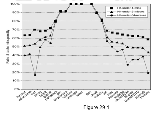
Non-blocking caches: They are also called lock-up free caches. For processors that support out-of-order completion, the CPU need not stall on a cache miss. For example, the CPU continues fetching instructions from the instruction cache while waiting for the data cache to return the missing data. There is a possibility of having a hit under a miss. This “hit under miss” optimization reduces the effective miss penalty by being helpful during a miss instead of ignoring the requests of the CPU. We can also have even further optimizations like, a “hit under multiple miss” or “miss under miss” optimization. That is, even when there are multiple outstanding misses, we still allow the processor to access. However, all this significantly increases the complexity of the cache controller as there can be multiple outstanding memory accesses. Also, there will be difficulties with performance evaluation. A cache miss does not necessarily stall the CPU and there is a possibility of occurrence of more than one miss request to the same block. This has to be handled carefully. The hardware must check on misses to avoid incoherency problems and to save time.
Figure 29.1 shows the average time in clock cycles for cache misses for an 8-KB data cache as the number of outstanding misses is varied. Floating-point programs benefit from the increasing complexity associated with multiple outstanding misses, while integer programs get almost all of the benefit from a simple hit-under-one-miss scheme.
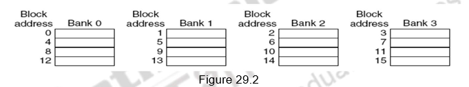
Multi-banked caches: Instead of treating the cache as a single block of memory, we can organize the cache as a collection of independent banks to support simultaneous access. The same concept that was used to facilitate parallel access and increased bandwidth in main memories is used here also. The ARM Cortex A8 supports 1-4 banks for L2. The Intel i7 supports 4 banks for L1 and 8 banks for L2.
Banking supports simultaneous accesses only when the addresses are spread across multiple banks. The mapping of addresses to banks affects the behavior of the memory system. A simple way to spread the accesses across multiple blocks is sequential interleaving as shown in Figure 29.2. The figure shows four-way interleaved cache banks using block addressing. Block 0 is in bank 0, block 1 in bank1, block 2 in bank 2 and block 3 in bank 3. Now, block 4 is in bank 0, and so on. Blocks 0, 4, 8 and 12 are mapped to bank 0, blocks 1, 5, 9, 13 are mapped to block1, and so on. So, block number mod number of banks decides the bank number. Assuming 64 bytes per block, each of these addresses would be multiplied by 64 to get byte addressing. Multiple banks also help in reducing the power consumption.
Hardware based prefetching: One other technique to reduce miss penalty is to prefetch items before they are requested by the processor. Both instructions and data can be prefetched, either directly into the caches or into an external buffer that can be accessed faster than main memory. With respect to instruction prefetches, the processor typically fetches two blocks on a miss – the requested block and the next consecutive block. The requested block is placed in the instruction cache , while the prefetched block is placed into the instruction stream buffer. If the requested block is present in the instruction stream buffer, the original cache request is canceled, the block is read from the stream buffer, and the next prefetch request is issued. People have shown that there has been a lot of improvement seen with such prefetches.
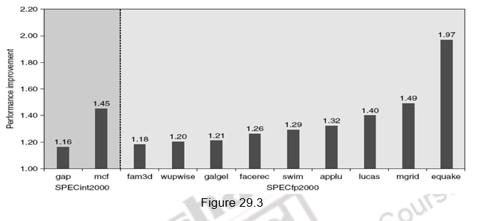
A similar approach can be applied to data accesses also. People have proved that a single data stream buffer caught about 25% of the misses from a 4-KB direct-mapped cache. Instead of having a single stream, there could be multiple stream buffers beyond the data cache, each prefetching at different addresses and this would increase the data hit rate. The UltraSPARC III uses such a prefetch scheme. A prefetch cache remembers the address used to prefetch the data. If a load hits in prefetch cache, the block is read from the prefetch cache, and the next prefetch request is issued. It calculates the “stride” of the next prefetched block using the difference between current address and the previous address. There can be up to eight simultaneous prefetches in UltraSPARC III. However, these prefetches should not interfere with demand based fetches. In that case, the performance will degrade. Figure 29.3 shows the performance improvement with prefetching in Pentium 4.
Compiler based prefetching: Just like hardware based prefetching, the compiler can also prefetch in order to reduce the miss rates and miss penalty. The compiler inserts prefetch instructions to request the data before they are needed. The two types of prefetch are:
- Register prefetch which loads the value into a register.
- Cache prefetch which loads data only into the cache and not the register.
Either of these can be faulting or non-faulting. That is, the address does or does not cause an exception for virtual address faults and protection violations. Non-faulting prefetches simply turn into no-ops if they would normally result in an exception. A normal load instruction could be considered a faulting register prefetch instruction. The most effective prefetch is “semantically invisible” to a program . It does not change the contents of registers and memory and it cannot cause virtual memory faults. Most processors today offer non-faulting cache prefetches. Like hardware-controlled prefetching, the goal is to overlap execution with the prefetching of data. Loops are the important targets, as they lend themselves to prefetch optimizations. If the miss penalty is small, the compiler just unrolls the loop once or twice and it schedules the prefetches with the execution. If the miss penalty is large, it uses software pipelining or unrolls many times to prefetch data for a future iteration. Issuing prefetch instructions incurs an instruction overhead, however, so care must be taken to ensure that such overheads do not exceed the benefits.
So far, we have looked at different techniques for reducing the miss penalty and miss rate via parallelism. Now, we shall discuss various techniques that are used to reduce the third component of AMAT, viz. hit time. This is about how to reduce time to access data that is in the cache. We shall look at techniques that are useful for quickly and efficiently finding out if data is in the cache, and if it is, getting that data out of the cache. Hit time is critical because it affects the clock rate of the processor . In many processors today, the cache access time limits the clock cycle rate, even for processors that take multiple clock cycles to access the cache. Hence, a fast hit time gains a lot of significance, beyond the average memory access time formula, because it helps everything.
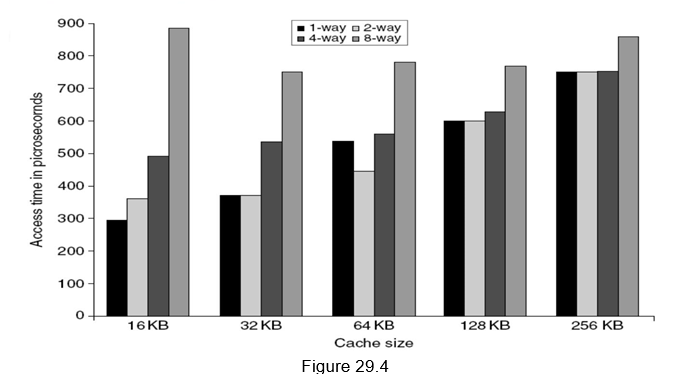
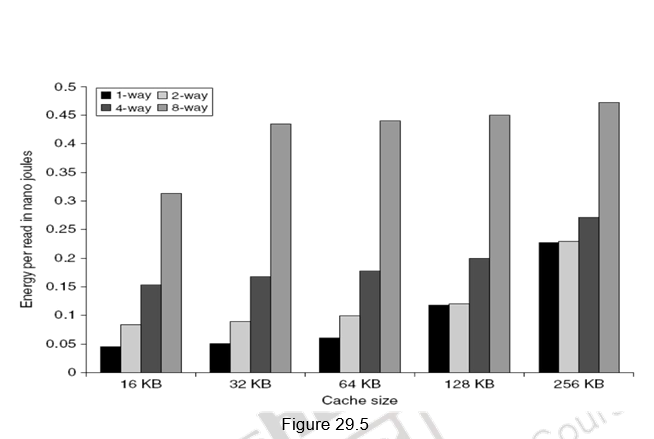
Small and simple first level caches: Small hardware is faster and hence a small and simple cache certainly helps the hit time. A smaller cache also enables it to be on chip and avoids the penalty associated with off chip caches. The c ritical timing path for accessing the cache includes addressing (indexing) tag memory, comparing tags and then getting the data. Direct-mapped caches can overlap the tag comparison and transmission of data. Since most of the data hits in the cache, saving a cycle on data access in the cache is a significant result. Lower associativity also reduces power because fewer cache lines are accessed. Figure 29.4 shows the effect of cache size and associativity on the access times. As the size/associativity increases, the access time increases. Figure 29.5 shows the effect of cache size and associativity on the energy per read. As the size/associativity increases, the energy per read increases.
Avoiding address translation during indexing of the caches: With the support for virtual memory, virtual addresses will have to first be translated to physical addresses and only then the indexing of the cache can happen. Going by the general guideline of making the common case fast, we can use virtual addresses for the cache, since hits are much more common than misses. Such caches are termed virtual caches, with physical cache used to identify the traditional cache that uses physical addresses.
As already pointed out, we have two tasks associated with accessing the cache – indexing the cache and the tag comparison. Thus, the issues are whether a virtual or physical address is used to index the cache and whether a virtual or physical index is used in the tag comparison. Full virtual addressing for both index and tags eliminates address translation time from a cache hit. But there are several reasons for not looking at such virtually addressed caches.
One reason is protection. Normally, the very essential page level protection is checked as part of the virtual to physical address translation. One solution when we use virtual caches is to copy the protection information from the TLB on a miss, add a field to hold it, and check it on every access to the virtually addressed cache. Another reason is that every time a process is switched, the virtual addresses refer to different physical addresses, requiring the cache to be flushed. This can be handled with a process-identifier tag (PID). If the operating system assigns these tags to processes, the PID distinguishes whether or not the data in the cache are for this program. A third reason why virtual caches are not more popular is that operating systems and user programs may use two different virtual addresses for the same physical address. These duplicate addresses, called synonyms or aliases, could result in two copies of the same data in a virtual cache. If one is modified, the other will have the wrong value. Hardware solutions to the synonym problem, called anti-aliasing, make sure that such problems do not occur. The Alpha 21264 uses a 64 KB instruction cache with an 8 KB page and two-way set associativity. Hence, the hardware must handle aliases involved with the 2 virtual address bits in both sets. It avoids aliases by simply checking all 8 possible locations on a miss–four entries per set, to be sure that none match the physical address of the data being fetched. If one is found, it is invalidated, so when the new data is loaded into the cache its physical address is guaranteed to be unique. Software can make this problem much easier by forcing aliases to share some address bits. Lastly, the final area of concern with virtual addresses is I/O. I/O typically uses physical addresses and thus would require mapping to virtual addresses to interact with a virtual cache.
One way to reap the benefits of both virtual and physical caches is to use part of the page offset, the part that is identical in both virtual and physical addresses to index the cache. When the cache is being indexed using the virtual address, the virtual part of the address is translated, and the tag match uses physical addresses. This is called a virtually indexed physically tagged cache. This alternative allows the cache read to begin immediately and yet the tag comparison is still with physical addresses. The limitation of this type of cache is that a direct-mapped cache cannot be larger than the page size.
Pipelining the cache access: The next technique that can be used to reduce the hit time, is to pipeline the cache access, so that the effective latency of a first level cache hit can be multiple clock cycles, giving fast cycle time and slow hits. For example, the pipeline for the Pentium takes one clock cycle to access the instruction cache, for the Pentium Pro through Pentium III it takes two clocks, and for the Pentium 4 to i7, it takes four clocks. This split increases the number of pipeline stages, leading to greater penalty on mis-predicted branches and more clock cycles between the issue of the load and the use of the data. This technique, in reality, increases the bandwidth of instructions rather than decreasing the actual latency of a cache hit. It also makes it easier to increase associativity.
Trace cache: The last technique that we discuss is the use of a trace cache. One of the main challenges in modern day processors is to find instruction level parallelism beyond four instructions per cycle, so that the integrated instruction unit is able to supply enough instructions every cycle without dependencies. One solution is called a trace cache. Instead of limiting the instructions in a static cache block to spatial locality, a trace cache finds a dynamic sequence of instructions including taken branches to load into a cache block. It is called a trace cache, because the cache blocks contain dynamic traces of the executed instructions as determined by the CPU, rather than containing static sequences of instructions as determined by memory. Hence, the branch prediction is folded into cache, and must be validated along with the addresses to have a valid fetch. The Intel Netburst microarchitecture, which is the foundation of the Pentium 4 and its successors, uses a trace cache.
Trace caches have much more complicated address mapping mechanisms, as the addresses are no longer aligned to power of 2 multiple of the word size. However, they have other benefits for utilization of the data portion of the instruction cache. With branches being very frequent, large blocks may be wasted in conventional caches. Space utilization is a real problem for processors like the AMD Athlon, whose 64 byte block would probably include16 to 24 80×86 instructions. The trend towards higher instruction issue makes the problem worse. Trace caches store instructions only from the branch entry point to the exit of the trace, thereby avoiding such under utilization. However, the downside of trace caches is that they store the same instructions multiple times in the instruction cache. Conditional branches making different choices result in the same instructions being part of separate traces, which each occupy space in the cache.
To summarize, we have defined the average memory access time in this module. The AMAT depends on the hit time, miss rate and miss penalty. Several optimizations exist to handle each of these factors . We discussed different techniques for reducing the miss penalty and miss rate via parallelism and for reducing the hit time . They are:
Ø Reducing the miss penalty or miss rate via parallelism
§ Non-blocking caches
§ Multi banked caches
§ Hardware & compiler prefetching
Ø Reducing the time to hit in the cache
§ Small and simple caches
§ Avoiding address translation
§ Pipelined cache access, and
§ Trace caches
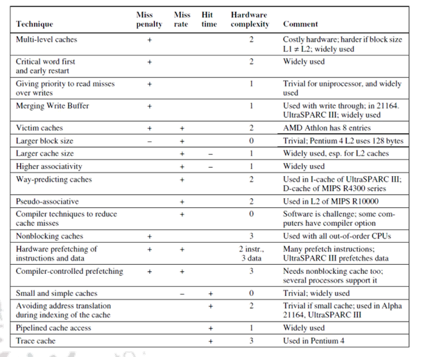
Figure 29.6
As a ready reckoner, Figure 29.6 gives a summary of all the cache optimization techniques that we have discussed in the past three modules.
Web Links / Supporting Materials
- Computer Organization and Design – The Hardware / Software Interface, David A. Patterson and John L. Hennessy, 4th Edition, Morgan Kaufmann, Elsevier, 2009.
- Computer Architecture – A Quantitative Approach , John L. Hennessy and David A.Patterson, 5th Edition, Morgan Kaufmann, Elsevier, 2011.
- Computer Organization, Carl Hamacher, Zvonko Vranesic and Safwat Zaky, 5th.Edition, McGraw- Hill Higher Education, 2011