12 Handling Data Hazards
Dr A. P. Shanthi
The objectives of this module are to discuss how data hazards are handled in general and also in the MIPS architecture.
We have already discussed in the previous module that true data dependences give rise to RAW hazards and name dependences (antidependence and output dependence) give rise to WAR hazards and WAW hazards, respectively.
Figure 12.1 gives a situation of having true data dependences. The use of the result of the ADD instruction in the next three instructions causes a hazard, since the register is not written until after those instructions read it. The write back for the ADD instruction happens only in the fifth clock cycle, whereas the next three instructions read the register values before that, and hence will read the wrong data. This gives rise to RAW hazards.
One effective solution to handle true data dependences is forwarding. Forwarding is the concept of making data available to the input of the ALU for subsequent instructions, even though the generating instruction hasn’t gotten to WB in order to write the memory or registers. This is also called short circuiting or by passing. This is illustrated in Figure 12.2.
The first instruction has finished execution and the result has been written into the EX/MEM buffer. So, during the fourth clock cycle, when the second instruction, SUB needs data, this can be forwarded from the EX/MEM buffer to the input of the ALU. Similarly, for the next AND instruction, the result of the first instruction is now available in the MEM/WB buffer and can be forwarded from there. For the OR instruction, the result is written into the register file during the first half of the clock cycle and the data from there is read during the second half. So, this instruction has no problem. In short, data will have to be forwarded from either the EX/MEM buffer or the MEM/WB buffer.
Figure 12.3 shows the hardware changes required to support forwarding. The inputs to the ALU have increased. The multiplexors will have to be expanded, in order to accommodate the additional inputs from the two buffers.
Figure 12.4 shows a case where the first instruction is a load and the data becomes available only after the fourth clock cycle. So, forwarding will not help and the second instruction will anyway have a stall of one cycle. For the next instruction, AND, data is forwarded from the MEM/WB buffer. There are thus instances where stalls may occur even with forwarding. However, forwarding is helpful in minimizing hazards and sometimes in totally eliminating them.
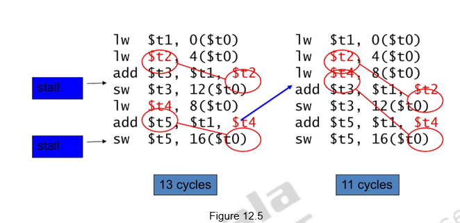
The other method of avoiding / minimizing stalls due to true data dependences is to reorder the code – separate the dependent instructions. This is illustrated in Figure 12.5. The snippet shown calculates A = B + E; C = B + F; The dependent instruction after the load can be reordered to avoid use of load result in the next instruction. This reordering has helped in reducing the number of clock cycles for execution from 13 to 11. Two stalls have been avoided.
Based on the discussion given earlier, we can identify the two pairs of hazard conditions as:
1a. EX/MEM.RegisterRd = ID/EX.RegisterRs
1b. EX/MEM.RegisterRd = ID/EX.RegisterRt
2a. MEM/WB.RegisterRd = ID/EX.RegisterRs
2b. MEM/WB.RegisterRd = ID/EX.RegisterRt
The notation used here is as follows: The first part of the name, to the left of the period, is the name of the pipeline register and the second part is the name of the field in that register. For example, “ID/EX.RegisterRs” refers to the number of one register whose value is found in the pipeline register ID/EX; that is, the one from the first read port of the register file. We shall discuss the various hazards based on the following sequence of instructions.

The first hazard in the sequence is on register $2, between the result of sub $2,$1,$3 and the first read operand of and $12,$2,$5. This hazard can be detected when the and instruction is in the EX stage and the prior instruction is in the MEM stage, so this is hazard 1a:EX/MEM.RegisterRd = ID/EX.RegisterRs = $2
The sub-or is a type 2b hazard:
MEM/WB.RegisterRd = ID/EX.RegisterRt = $2
The two dependences on sub-add are not hazards because the register file supplies the proper data during the ID stage of add. There is no data hazard between sub and sw because sw reads $2 the clock cycle after sub writes $2. However, as some instructions do not write into the register file, this rule has to be modified. Otherwise, sometimes it would forward when it was unnecessary. One solution is simply to check to see if the RegWrite signal will be active. Examining the WB control field of the pipeline register during the EX and MEM stages determines if RegWrite is asserted or not. Also, MIPS requires that every use of $0 as an operand must yield an operand value of zero. In the event that an instruction in the pipeline has $0 as its destination (for example, sll $0, $1, 2), we want to avoid forwarding its possibly nonzero result value. The conditions above thus work properly as long as we add EX/MEM.RegisterRd ≠ 0 to the first hazard condition and MEM/WB.RegisterRd ≠ 0 to the second.
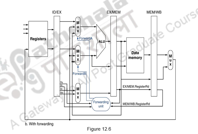
Figure 12.6 shows the forwarding paths added to the MIPS pipeline. The ForwardA and ForwardB are the additional control signals added. These control signals take on a value of 00, 10 or 01, depending on whether the multiplexor will pass on the data from the ID/EX, EX/MEM or MEM/WB buffers, respectively.
The conditions for detecting hazards and the control signals to resolve them are as follows:
1. EX hazard:
if (EX/MEM.RegWrite
and (EX/MEM.RegisterRd _ 0)
and (EX/MEM.RegisterRd = ID/EX.RegisterRs)) ForwardA = 10
if (EX/MEM.RegWrite
and (EX/MEM.RegisterRd _ 0)
and (EX/MEM.RegisterRd = ID/EX.RegisterRt)) ForwardB = 10
This case forwards the result from the previous instruction to either input of the ALU. If the previous instruction is going to write to the register file and the write register number matches the read register number of ALU inputs A or B, provided it is not register 0, then direct the multiplexor to pick the value instead from the pipeline register EX/MEM.
2. MEM hazard:
if (MEM/WB.RegWrite
and (MEM/WB.RegisterRd _ 0)
and (MEM/WB.RegisterRd = ID/EX.RegisterRs)) ForwardA = 01
if (MEM/WB.RegWrite
and (MEM/WB.RegisterRd _ 0)
and (MEM/WB.RegisterRd = ID/EX.RegisterRt)) ForwardB = 01
As mentioned above, there is no hazard in the WB stage because we assume that the register file supplies the correct result if the instruction in the ID stage reads the same register written by the instruction in the WB stage. Such a register file performs another form of forwarding, but it occurs within the register file.
Another complication is the potential data hazards between the result of the instruction in the WB stage, the result of the instruction in the MEM stage, and the source operand of the instruction in the ALU stage. For example, when summing a vector of numbers in a single register, a sequence of instructions will all read and write to the same register as indicated below:
add $1,$1,$2
add $1,$1,$3
add $1,$1,$4
. . .
In this case, the result is forwarded from the MEM stage because the result in the MEM stage is the more recent result. Thus the control for the MEM hazard would be (with the additions highlighted)
if (MEM/WB.RegWrite
and (MEM/WB.RegisterRd _ 0)
and (EX/MEM.RegisterRd _ ID/EX.RegisterRs)
and (MEM/WB.RegisterRd = ID/EX.RegisterRs)) ForwardA = 01
if (MEM/WB.RegWrite
and (MEM/WB.RegisterRd _ 0)
and (EX/MEM.RegisterRd _ ID/EX.RegisterRt)
and (MEM/WB.RegisterRd = ID/EX.RegisterRt)) ForwardB = 01
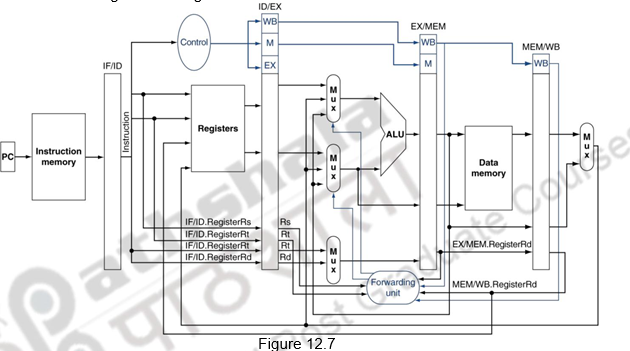
Figure 12.7 shows the datapath modified to resolve hazards via forwarding. Compared with the datapath already shown, the additions are the multiplexors to the inputs to the ALU.
As we already discussed, one case where forwarding cannot help eliminate hazards is when an instruction tries to read a register following a load instruction that writes the same register. This is illustrated in Figure 12.8. The data is still being read from memory in clock cycle 4 while the ALU is performing the operation for the following instruction. Something must stall the pipeline for the combination of load followed by an instruction that reads its result. Hence, in addition to a forwarding unit, we need a hazard detection unit. It operates during the ID stage so that it can insert the stall between the load and its use. Checking for load instructions, the control for the hazard detection unit is this single condition:
if (ID/EX.MemRead and
((ID/EX.RegisterRt = IF/ID.RegisterRs) or
(ID/EX.RegisterRt = IF/ID.RegisterRt)))
stall the pipeline
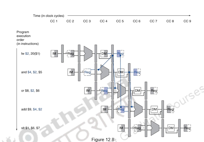
The first line tests to see if the instruction is a load. The only instruction that reads data memory is a load. The next two lines check to see if the destination register field of the load in the EX stage matches either source register of the instruction in the ID stage. If the condition holds, the instruction stalls 1 clock cycle. After this 1-cycle stall, the forwarding logic can handle the dependence and execution proceeds. If there were no forwarding, then the instructions would need another stall cycle.
If the instruction in the ID stage is stalled, then the instruction in the IF stage must also be stalled; otherwise, we would lose the fetched instruction. Preventing these two instructions from making progress is accomplished simply by preventing the PC register and the IF/ID pipeline register from changing. Provided these registers are preserved, the instruction in the IF stage will continue to be read using the same PC, and the registers in the ID stage will continue to be read using the same instruction fields in the IF/ID pipeline register. The back half of the pipeline starting with the EX stage must be executing instructions that have no effect. This is done by executing nops. Deasserting all the nine control signals (setting them to 0) in the EX, MEM, and WB stages will create a “do nothing” or nop instruction. By identifying the hazard in the ID stage, we can insert a bubble into the pipeline by changing the EX, MEM, and WB control fields of the ID/EX pipeline register to 0. These control values are percolated forward at each clock cycle with the proper effect – no registers or memories are written if the control values are all 0.
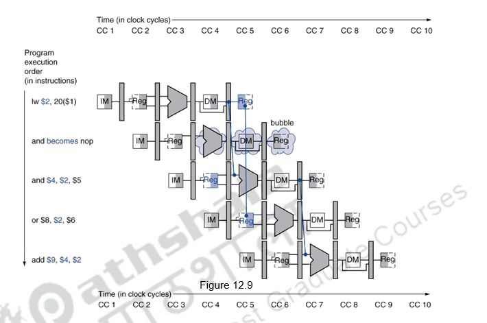
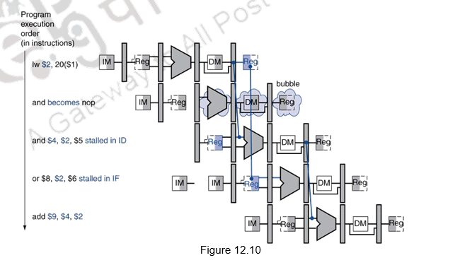
Figures 12.9 and 12.10 show what really happens in the hardware: the pipeline execution slot associated with the AND instruction is turned into a NOP and all instructions beginning with the AND instruction are delayed one cycle. The hazard forces the AND and OR instructions to repeat in clock cycle 4 what they did in clock cycle 3: and reads registers and decodes, and OR is refetched from instruction memory. Such repeated work is what a stall looks like, but its effect is to stretch the time of the AND and OR instructions and delay the fetch of the ADD instruction. Like an air bubble in a water pipe, a stall bubble delays everything behind it and proceeds down the instruction pipe one stage each cycle until it exits at the end.
Figure 12.11 highlights the pipeline connections for both the hazard detection unit and the forwarding unit
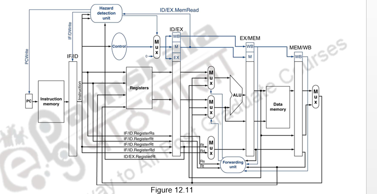
As discussed before, the forwarding unit controls the ALU multiplexors to replace the value from a general-purpose register with the value from the proper pipeline register. The hazard detection unit controls the writing of the PC and IF/ID registers plus the multiplexor that chooses between the real control values and all 0s. The hazard detection unit stalls and deasserts the control fields if the load-use hazard test is true.
It should be noted that stalls reduce performance, but are required to get correct results. Also remember that the compiler can arrange code to avoid hazards and stalls and it requires knowledge of the pipeline structure to do this. For the other types of data hazards, viz. WAR and WAW hazards where there is no true sharing of data, they can be resolved by register renaming, which can be handled by the hardware or the compiler. This renaming can happen with memory operands also, which is more difficult to handle, because it is difficult to resolve the ambiguity associated with memory operands.
To summarize, in this module we have discussed about how data hazards can be handled by forwarding. This technique requires needs extra hardware paths and control. All cases may not be handled and stalls may be necessary. To avoid WAR and WAW hazards, register renaming by software or hardware can be done. RAW hazards can also be handled by reorganization of code, either by software or hardware. The hardware reorganization of code during execution will be discussed in later modules.
Web Links / Supporting Materials
- Computer Organization and Design – The Hardware / Software Interface, David A. Patterson and John L. Hennessy, 4th.Edition, Morgan Kaufmann, Elsevier, 2009.
- Computer Organization, Carl Hamacher, Zvonko Vranesic and Safwat Zaky, 5th.Edition, McGraw- Hill Higher Education, 2011.