27 Virtual Memory II
Dr A. P. Shanthi
The objectives of this module are to discuss the other implementations of virtual memory, viz, segmentation and segmented paging and compare and contrast the various implementations of virtual memory. The concept of virtual machines will be introduced. Also, the various techniques used for improving the main memory access time will be discussed.
Address Mapping Using Segments: The previous module discussed in detail about the virtual memory management system, where the main memory and the programs were divided into pages of equal size. But, the fixed page size causes certain difficulties with respect to program size and the logical structure of programs. It is more convenient to divide programs and data into logical parts called segments. A segment is a set of logically related instructions or data elements associated with a given name. Segments may be generated by the programmer or by the operating system. Examples of seg-ments are a subroutine, an array of data, a table of symbols, or a user’s program. As in paging, the address generated by a segmented program is called a logical address. This is similar to a virtual address except that logical address space is associated with variable-length segments rather than fixed -length pages. The logical address consists of the segment number and the offset. The segment number is mapped to a physical address using segment descriptor tables. These tables do the same function as the page tables in paging. Because the segments can vary is size, a bounds check is also needed to make sure that the offset is within the segment. The function of the memory management unit is to map logical addresses into physical addresses similar to the virtual memory mapping concept. The segmentation concept is illustrated in Figure 31.1.
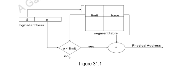
In addition to relocation information, each segment descriptor entry has protection information associated with it. Segmentation offers the advantage of sharing commonly used data and programs. Shared programs are placed in a unique segment in each user’s logical address space so that a single physical copy can be shared.
Segments cannot be broken further and the entire segment has to be either in memory or on disk. The variable sizes of the segments leads to external fragmentation in memory, whereas, in paging we have only internal fragmentation, where the last page alone may not be completely filled. When it comes to bringing in a new segment into main memory also, we have more complications. In the case of paging, all the blocks are of the same size. Therefore, any block can replace any block. However, as segments are of varying sizes, the operating system has to identify a segment large enough to accommodate the incoming segment. This is done with the following techniques:
- First fit – The first segment that is big enough to accommodate the incoming segment is chosen.
- Best fit – The best fitting segment, that is, the one leaving the least amount of free space is chosen. For example, if the segment size is 4K, and the available segments are of sizes 5K and 8K, the 5K segment will be chosen.
- Worst fit – The one that is the worst fit, leaving the maximum space will be chosen. In the previous example, the segment of size 8K will be chosen.
Note that the TLB is used in the case of segmentation also to speed up the memory access.
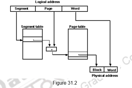
Address Mapping Using Segmented Paging: It is also possible to have a third memory management technique called segmented paging. As the name suggests, this is a combination of both segmentation and paging. It was already mentioned that the property of logical space is that it uses variable-length segments. The length of each segment is allowed to grow and contract according to the needs of the program being executed. One way of specifying the length of a segment is by associating with it a number of equal-sized pages. To see how this is done, consider the logical address shown in Figure 31.2. The logical address is partitioned into three fields. The segment field specifies a segment number. The page field specifies the page within the segment and the word field gives the specific word within the page. A page field of k bits can specify up to 2k pages. A segment number may be associated with just one page or with as many as 2k pages. Thus the length of a segment would vary according to the number of pages that are assigned to it.
The mapping of the logical address into a physical address is done by means of two tables. The segment number of the logical address specifies the address for the segment table. The entry in the segment table is a pointer address for a page table base. This new address is often referred to as a linear address . The page table base is added to the page number given in the logical address. The sum produces a pointer address to an entry in the page table. The value found in the page table provides the block number in physical memory. The concatenation of the block field with the word field produces the final physical mapped address.
We thus use pages to describe components of the segments . This makes segments easy to manage and we can swap memory between segments . We need to allocate page table entries only for those pieces of the segments that have themselves been allocated. Segments that are shared can be represented with shared page tables. The two mapping tables may be stored in main memory. Therefore, a memory reference from the CPU will require three accesses to memory – one from the segment table, one from the page table, and the third from main memory. This would slow the system even more. To avoid this speed penalty, the TLB is used in this case also.
Memory Management System: In a multiprogramming environment where many programs reside in memory, it becomes necessary to move programs and data around the memory, to vary the amount of memory in use by a given program, and to prevent a program from changing other programs. The demands on computer memory brought about by multiprogramming have created the need for a memory management system. A memory management system is a collection of hardware and software procedures for managing the various programs residing in memory. The memory management software is part of an overall operating system available in many computers. The hardware includes the page tables, segment tables and TLBs in the MMU as pointed out in the previous section. Putting everything together, we can say that the basic components of a memory management system are:
1. A facility for dynamic storage relocation that maps logical memory references into physical memory addresses
2. A provision for sharing common programs stored in memory by differ ent users
3. Protection of information against unauthorized access between users and preventing users from changing operating system functions.
The first function of dynamic storage relocation is what we discussed in the previous section.
The sharing of common programs is an integral part of a multiprogramming system. For example, several users wishing to compile their C programs should be able to share a single copy of the compiler rather than each user having a separate copy in memory. Other system programs residing in memory are also shared by all users in a multiprogramming system without having to produce multiple copies.
The third issue in multiprogramming is protecting one program from unwanted interaction with another. An example of unwanted interaction is one user’s unauthorized copying of another user’s program. Another aspect of protection is concerned with preventing the occasional user from performing operating system functions and thereby interrupting the orderly sequence of operations in a computer installation. The secrecy of certain programs must be kept from unauthorized personnel to prevent abuses in the confidential activities of an organization. This feature is again supported in virtual memory by providing support for the addition of protection and access rights information in every page/segment. The following features are supported by the architecture in order to provide protection:
- Provide at least two modes, indicating whether the running process is a user process or an operating system process, called a kernel process or a supervisor process.
- Provide a portion of the processor state that a user process can use but not modify. This state includes an user/supervisor mode bit(s), an exception enable/disable bit, and memory protection information. Users are prevented from writing this state because the operating system cannot control user processes if users can give themselves supervisor privileges, disable exceptions, or change memory protection.
- Provide mechanisms whereby the processor can go from user mode to supervisor mode and vice versa. The first direction is typically accomplished by a system call, implemented as a special instruction that transfers control to a dedicated location in supervisor code space. The PC is saved from the point of the system call, and the processor is placed in supervisor mode. The return to user mode is like a subroutine return that restores the previous user/supervisor mode.
- Provide mechanisms to limit memory accesses to protect the memory state of a process without having to swap the process to disk on a context switch.
Thus, the above discussion clearly shows that we can enforce protection through the operating system with the support of architecture. However, the operating systems consist of tens of millions of lines of code and there are quite a lot of bugs here. Flaws in the OS have led to vulnerabilities that are routinely exploited. This problem, and the possibility that not enforcing protection could be much more costly than in the past, has led some to look for a protection model with a much smaller code base than the full OS, such as Virtual Machines.
Virtual Machines and Protection: Although virtual machines were not very popular in single-user computers, they have recently gained popularity due to the following reasons:
- the increasing importance of isolation and security in modern systems
- the failures in security and reliability of standard operating systems
- the sharing of a single computer among many unrelated users, and
- the dramatic increases in raw speed of processors, which makes the overhead of VMs more acceptable.
VMs provide a complete system-level environment at the binary instruction set architecture (ISA) level. They present the illusion that the users of a VM have an entire computer to themselves, including a copy of the operating system. A single computer runs multiple VMs and can support a number of different operating systems. On a conventional platform, a single OS “owns” all the hardware resources, but with a VM, multiple operating systems share the hardware resources. The software that supports VMs is called a virtual machine monitor (VMM) or hypervisor; the VMM is the heart of Virtual Machine technology. The underlying hardware platform is called the host, and its resources are shared among the guest VMs. The VMM determines how to map virtual resources to physical resources. A physical resource may be time -shared, partitioned, or even emulated in software. The VMM is much smaller than a traditional OS. Each guest OS maintains its own set of page tables. The VMM adds a level of memory between physical and virtual memory called “real memory” and the VMM maintains shadow page table that maps guest virtual addresses to physical addresses.
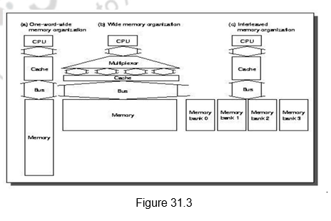
Improving the access times of main memory: Last of all, we shall look at various techniques that are used to improve the performance of main memory. Figure 31.3 shows various methods used to increase the bandwidth of main memory. The first method is a simple one where the CPU, cache, bus and memory have the same width, say 32 or 64 bits. The second one shows a wide memory organization, where the CPU/Mux width is 1 word. However, the Mux/Cache, bus and memory width are N words. The Alpha processor uses 64 bits & 256 bits and the UtraSPARC uses 64 bits and 512 bits. The third organization shows an interleaved organization, where the CPU, cache and bus have a width of 1 word, but the memory has N Modules (say, 4 Modules); for example, word interleaved. First-level caches are often organized with a physical width of 1 word because most CPU accesses are of that size. There is additional cost involved in the wider connection between the CPU and memory, typically called a memory bus. This may help for the second-level caches, since the multiplexing can be between the first and second level caches, and not on the critical path.
Memory chips can be organized in banks to read or write multiple words at a time rather than a single word. The mapping of the addresses to banks affects the behavior of the memory system. This mapping is called the Interleaving Factor. Interleaving Memory normally means banks of memory that are word interleaved. It is used to optimize sequential memory accesses. A cache read miss is an ideal match to word-interleaved memory, because the words in a block are read sequentially. Write-back caches make writes as well as reads sequential, getting even more efficiency from word-interleaved memory. However, the disadvantages are the shrinking number of chips and the difficulty of main memory expansion.
We can also look at independent memory banks, where each bank needs separate address lines and possibly a separate data bus. This is particularly useful with nonblocking caches that allow the CPU to proceed beyond a cache miss, potentially allowing multiple cache misses to be serviced simultaneously. Otherwise, the multiple reads will be serviced by a single memory port and will get only a small benefit of overlapping access with transmission. Normally, independent of memory technology, higher bandwidth is made available using memory banks, by making memory and its bus wider, or doing both.
Summary
- Techniques that automatically move program-and data blocks into the physical main memory when they are required for execution are called virtual-memory techniques.
- Virtual memory is a concept implemented using hardware and software.
- The restriction placed on the program size is not based on the RAM size, but based on the virtual memory size.
- There are three different ways of implementing virtual memory.
- The MMU does the logical to physical address translation.
- Paging uses fixed size pages to move between main memory and secondary storage.
- Paging uses page tables to map the logical addresses to physical addresses.
- Segmentation uses varying sized segments.
- Segmented paging combines paging and segmentation.
- TLB is used to store the most recent logical to physical address translations.
- Virtual memory helps in separating the user and supervisor programs and also one user’s program from another.
- Virtual machines also help in providing isolation and protection.
- Main memory bandwidth can be increased by different techniques .
- We can use a wider main memory or an interleaved main memory to increase the bandwidth.
Web Links / Supporting Materials
- Computer Organization and Design – The Hardware / Software Interface, David A. Patterson and John L. Hennessy, 4th Edition, Morgan Kaufmann, Elsevier, 2009.
- Computer Architecture – A Quantitative Approach , John L. Hennessy and David A.Patterson, 5th Edition, Morgan Kaufmann, Elsevier, 2011.
- Computer Organization, Carl Hamacher, Zvonko Vranesic and Safwat Zaky, 5th.Edition, McGraw- Hill Higher Education, 2011.